
5 Hard-to-Solve PCBA Board Issues Related to Chip Ceramic Capacitors
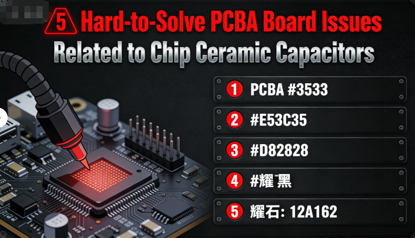
5 Hard-to-Solve PCBA Board Issues Related to Chip Ceramic Capacitors
Table of Contents
- PCBA frequent crash/restart & hard troubleshooting
- Batch cold soldering & ineffective rework
- High-temperature failure with high-temp components
- Severe signal distortion & useless circuit adjustment
- Repeated MLCC bulging/leaking after replacement
- Quick Reference: Issues & Solutions
- Conclusion: Solve PCBA Pain Points with Barron MLCC
- Google SEO Optimization Highlights
For electronics engineers, PCB designers, and production technicians, few things are more frustrating than hard-to-solve PCBA board issues—problems that persist despite hours of troubleshooting, rework, and component replacement. More often than not, these stubborn issues trace back to a single, overlooked component: the chip ceramic capacitor (MLCC).
Chip ceramic capacitors are the backbone of every PCBA board, responsible for filtering, voltage stabilization, and signal integrity. Yet their role in PCBA failures is often underestimated—especially when the issues are subtle, invisible, or seem unrelated to capacitors at first glance. Engineers spend days debugging chips, power modules, and connectors, only to find that the real culprit is a mismatched, low-quality, or improperly selected chip ceramic capacitor.
As a trusted global supplier of chip ceramic capacitors with decades of experience supporting PCBA manufacturers, Barron MLCC (www.barronmlcc.com) has compiled the 5 most common hard-to-solve PCBA board issues related to chip ceramic capacitors. Each issue focuses on the “stubborn” pain points you’re likely facing—problems that resist quick fixes—and provides actionable, expert solutions to resolve them once and for all. Whether you’re troubleshooting mass production failures or optimizing high-reliability PCBA designs, this guide will save you time, reduce scrap rates, and improve product stability.
1. Why does the PCBA board frequently crash or restart, and why is it hard to troubleshoot the root cause?
One of the most frustrating PCBA issues is frequent crashing, restarting, or intermittent shutdowns—especially when basic troubleshooting (checking chips, power supplies, and connectors) shows no obvious problems. Engineers often spend hours running diagnostic tests, reworking solder joints, and even replacing core components, only to see the issue persist. This is one of the most common “ghost” problems in PCBA manufacturing, and its root cause is almost always invisible to the naked eye.
The Hard-to-Detect Root Cause
The primary reason this issue is so hard to troubleshoot is that it’s caused by subtle ESR (Equivalent Series Resistance) drift in chip ceramic capacitors—especially those used in power supply filtering or voltage stabilization circuits. Unlike a bulging or cracked capacitor, ESR drift is invisible: the capacitor looks intact, but its internal resistance gradually increases over time (or even from the start, with low-quality capacitors).
As ESR increases beyond 50mΩ (for most PCBA applications), the capacitor can no longer effectively filter out voltage ripples or stabilize power supplies. This leads to unstable voltage delivery to the chip, causing the PCBA board to crash or restart intermittently. Since ESR drift can’t be detected with a basic multimeter (you need an LCR meter), engineers often overlook it entirely.
The Expert Solution (Finally, a Fix That Works)
- Test ESR with an LCR Meter: Focus on chip ceramic capacitors in power supply and filtering positions (these are the most prone to ESR drift). Use an LCR meter to measure ESR—any capacitor with ESR exceeding 50mΩ should be replaced immediately.
- Use Low-ESR, High-Stability Capacitors: Replace faulty capacitors with Barron MLCC’s low-ESR series (//www.barronmlcc.com). Our capacitors are engineered with high-purity dielectrics and precision electrodes to minimize ESR drift, ensuring stable performance over time.
- Add Redundancy in Critical Circuits: For high-reliability PCBA boards (e.g., medical equipment, industrial controls), add a secondary filtering capacitor in parallel with the main capacitor. This provides a backup if one capacitor experiences ESR drift.
2. Why does the PCBA board have batch cold soldering after welding, and why can’t it be solved by rework?
Batch cold soldering is a nightmare for PCBA manufacturers—it leads to low production efficiency, high scrap rates, and frustrated technicians. Engineers often assume the problem is with the soldering process (e.g., temperature, solder paste quality) and spend hours reworking solder joints or adjusting reflow curves, only to see the same cold soldering issues in the next batch. The truth is, this problem rarely stems from the soldering process itself—it’s a capacitor-related compatibility issue.
The Hidden Root Cause
Batch cold soldering that resists rework is almost always caused by one of two capacitor-related issues:
- Mismatched Capacitor Package and PCB Pad Design: If the chip ceramic capacitor’s package size (e.g., 0402, 0603) doesn’t align with the PCB pad dimensions, the solder can’t properly wet the capacitor’s electrodes. This leads to weak, dull solder joints (cold soldering) that persist even after rework.
- Poor Wetting of Capacitor Electrodes: Low-quality chip ceramic capacitors use cheap, thin electrode materials (e.g., pure tin) that don’t wet well with solder. Even with perfect soldering parameters, these electrodes fail to form a strong bond with the solder, leading to cold soldering.
Engineers often overlook these issues because they’re focused on the soldering process, not the capacitor itself. Reworking individual solder joints doesn’t address the root cause—compatibility or electrode quality—so the problem repeats in every batch.
The Expert Solution (Stop Reworking, Start Fixing)
- Match Capacitor Packages to PCB Pads: Use Barron MLCC’s free PCB pad design guidelines (available for download at //www.barronmlcc.com) to ensure your PCB pads are sized correctly for the chip ceramic capacitor package you’re using. For example, 0603 capacitors require pad lengths of 0.8-1.0mm and widths of 0.4-0.5mm.
- Choose Capacitors with High-Quality Electrodes: Select chip ceramic capacitors with thick, tin-lead alloy electrodes (e.g., Barron MLCC’s standard series). These electrodes wet easily with solder, forming strong, reliable solder joints that resist cold soldering.
- Optimize Reflow Curves for Capacitors: Adjust your reflow soldering curve to match the thermal requirements of your chip ceramic capacitors. Barron MLCC provides detailed thermal profiles for all our capacitors, ensuring the solder melts fully and wets the electrodes properly.
3. Why does the PCBA board fail in high-temperature environments, even after replacing high-temperature components?
PCBA boards used in high-temperature environments (e.g., automotive underhood systems, industrial furnaces, outdoor electronics) often fail prematurely—even after engineers replace chips, power modules, and other components with high-temperature-rated alternatives. This is a common, hard-to-solve issue because the real culprit is often the chip ceramic capacitors, which are overlooked in high-temperature design.
The Overlooked Root Cause
High-temperature PCBA failure, despite using high-temperature components, is caused by two capacitor-related issues:
- Exaggerated Temperature Ratings: Many cheap chip ceramic capacitors claim to have a high-temperature range (e.g., -40°C to 125°C) but use low-quality dielectrics that degrade quickly at temperatures above 85°C. Engineers assume these capacitors meet the requirements, only to see them fail in real-world high-temperature conditions.
- Thermal Stress Damage: Chip ceramic capacitors with high thermal expansion coefficients (TEC) expand and contract differently from the PCB board when exposed to temperature fluctuations. This creates thermal stress, which cracks the ceramic body or weakens solder joints over time—leading to PCBA failure.
Since engineers focus on replacing core components (chips, power supplies) with high-temperature alternatives, they often overlook the capacitors—allowing these hidden issues to cause repeated failures.
The Expert Solution (High-Temperature Stability Guaranteed)
- Choose Capacitors with Genuine High-Temperature Ratings: Select chip ceramic capacitors with a verified temperature range of -55°C to 150°C (not just claimed). Barron MLCC’s high-temperature series (//www.barronmlcc.com) uses high-purity X7R/X5R dielectrics that maintain stability even in extreme heat, with 100% batch testing to ensure temperature performance.
- Optimize PCBA Layout for Heat Dissipation: Avoid clustering chip ceramic capacitors in high-heat areas of the PCBA board. Reserve at least 1mm of spacing between capacitors to allow air circulation and reduce heat buildup.
- Use Low-TEC Capacitors: Choose chip ceramic capacitors with a thermal expansion coefficient (TEC) matching the PCB board (e.g., FR-4). Barron MLCC’s high-temperature capacitors have a low TEC, minimizing thermal stress and preventing damage from temperature fluctuations.
4. Why does the PCBA board have severe signal distortion that cannot be resolved by adjusting the circuit?
Signal distortion is a critical issue for high-frequency PCBA boards (e.g., 5G devices, audio equipment, sensors). Engineers often spend days adjusting signal lines, optimizing impedance, and replacing chips—only to see severe distortion (e.g., noise, data loss, signal attenuation) persist. This issue is hard to solve because the root cause isn’t in the circuit design—it’s in the chip ceramic capacitors’ parasitic parameters.
The Invisible Root Cause
Severe signal distortion that resists circuit adjustments is caused by excessive parasitic inductance (ESL) and parasitic capacitance in chip ceramic capacitors. High-frequency signals are extremely sensitive to these parasitic parameters, which act as unintended filters or oscillators—distorting the signal before it reaches the chip.
Engineers often overlook this because they focus on the circuit design (e.g., signal line length, impedance matching) rather than the capacitors. Large-package capacitors (e.g., 0805, 1206) generate more parasitic inductance, while low-quality dielectrics increase parasitic capacitance—both of which distort high-frequency signals. Adjusting the circuit won’t fix these parasitic effects, so the distortion persists.
The Expert Solution (Restore Signal Integrity)
- Use Small-Package, Low-ESL Capacitors: For high-frequency PCBA boards, replace large-package capacitors with small-package, low-ESL chip ceramic capacitors (0402 or 0603). These minimize parasitic inductance, ensuring clean signal transmission.
- Choose C0G/NP0 Dielectric Capacitors: Select chip ceramic capacitors with C0G/NP0 dielectrics (Barron MLCC’s high-frequency series: //www.barronmlcc.com). These dielectrics have stable parasitic parameters, even at high frequencies, and reduce signal distortion.
- Optimize Capacitor Layout: Place chip ceramic capacitors close to the ground plane and away from signal lines. This reduces parasitic interference and ensures the capacitor’s filtering function doesn’t distort the signal.
5. Why do chip ceramic capacitors on PCBA boards bulge or leak after long-term use, even after repeated replacement?
Another common hard-to-solve PCBA issue is chip ceramic capacitors bulging, leaking, or failing after long-term use—even when engineers replace them with new capacitors. This problem is frustrating because it suggests a deeper issue than just a faulty capacitor, yet the root cause is often overlooked in the replacement process.
The Persistent Root Cause
Repeated capacitor bulging or leaking is caused by two easily overlooked issues:
- Insufficient Voltage Redundancy: Engineers often replace capacitors with the same voltage rating as the PCBA board’s operating voltage (e.g., 12V capacitors for a 12V board). However, voltage spikes (common in power supply circuits) can exceed the capacitor’s rated voltage, causing it to bulge or leak over time. Without voltage redundancy, even high-quality capacitors will fail prematurely.
- Low-Quality Capacitor Materials: Using cheap, low-quality chip ceramic capacitors with impure dielectrics or thin electrodes. These capacitors degrade quickly under normal operating conditions, even with proper voltage redundancy—leading to repeated failures.
Engineers often make the mistake of replacing failed capacitors with the same voltage rating and cheap alternatives, failing to address the root cause of the problem. This leads to a cycle of repeated failures and replacements.
The Expert Solution (End the Replacement Cycle)
- Reserve 15%-20% Voltage Redundancy: Always choose a chip ceramic capacitor with a voltage rating 15%-20% higher than the PCBA board’s maximum operating voltage. For example, use 16V capacitors for a 12V board, or 25V capacitors for an 18V board. This protects against voltage spikes and extends capacitor life.
- Choose High-Quality, High-Reliability Capacitors: Replace cheap capacitors with Barron MLCC’s high-reliability series (//www.barronmlcc.com). Our capacitors use pure dielectrics and thick electrodes, with strict quality control to ensure long-term stability—even in harsh operating conditions.
- Monitor PCBA Voltage Spikes: Use a oscilloscope to monitor voltage spikes in the PCBA board’s power supply circuit. If spikes exceed 10% of the operating voltage, add a transient voltage suppressor (TVS) to protect the capacitors.
Quick Reference: Hard-to-Solve PCBA Issues & Solutions
| PCBA Issue | Hard-to-Detect Root Cause | Expert Solution |
|---|---|---|
| Frequent crash/restart | Subtle ESR drift in capacitors | Test ESR with LCR meter; use Barron MLCC low-ESR capacitors |
| Batch cold soldering (rework doesn’t help) | Mismatched capacitor package/PCB pad; poor electrode wetting | Follow Barron MLCC pad guidelines; use high-quality electrode capacitors |
| High-temperature failure | Exaggerated capacitor temperature ratings; thermal stress | Use Barron MLCC high-temperature capacitors; optimize layout for heat dissipation |
| Severe signal distortion | Excessive capacitor parasitic ESL/ESR | Use small-package, low-ESL capacitors; choose C0G/NP0 dielectrics |
| Repeated capacitor bulging/leaking | Insufficient voltage redundancy; low-quality capacitors | Reserve 15-20% voltage redundancy; use Barron MLCC high-reliability capacitors |
Conclusion: Solve PCBA Pain Points with Barron MLCC’s Expertise
The hard-to-solve PCBA board issues related to chip ceramic capacitors—frequent crashes, batch cold soldering, high-temperature failure, signal distortion, and repeated capacitor bulging—all have one thing in common: they’re caused by overlooked capacitor-related issues. Engineers often waste time troubleshooting the wrong components, but the real solution lies in selecting the right chip ceramic capacitors, optimizing their layout, and addressing hidden root causes like ESR drift, parasitic parameters, and voltage redundancy.
At Barron MLCC (www.barronmlcc.com), we don’t just supply high-quality chip ceramic capacitors—we provide the expertise and support you need to solve even the most stubborn PCBA issues. Our capacitors are engineered to minimize the hidden problems that cause PCBA failures, with low ESR, stable parasitic parameters, genuine high-temperature ratings, and strict quality control. We also offer free technical resources—pad design guidelines, thermal profiles, ESR test reports—to help you optimize your PCBA designs and avoid common pitfalls.
Whether you’re troubleshooting mass production failures or designing high-reliability PCBA boards, Barron MLCC has the solution. Explore our full range of chip ceramic capacitors tailored for PCBA applications: www.barronmlcc.com/chip-ceramic-capacitors. Have a hard-to-solve PCBA issue? Contact our technical team at www.barronmlcc.com/contact-us or send an email to www.barronmlcc.com—our experts will help you resolve it quickly.
Get Professional PCBA & MLCC Technical Support
Struggling with stubborn PCBA issues caused by chip ceramic capacitors? Our expert engineering team provides 1-on-1 technical guidance, free PCB pad design guidelines, thermal profile customization, and free MLCC sample testing to solve your PCBA pain points efficiently.
- ✉️ Technical Support Email: www.barronmlcc.com
- 🌐 Official Website: www.barronmlcc.com
- 🔗 PCBA-Specific MLCCs: barronmlcc.com/chip-ceramic-capacitors
- 📞 Contact Our Experts: barronmlcc.com
- 📦 Free MLCC Sample Application: barronmlcc.com/sample
- 📐 PCB Pad Design Guidelines: barronmlcc.com
Top 5 Most Common Usage Issues with Chip Ceramic Capacitors
THE SILENT HERO OF ELECTRONICS WHY TOP SOURCING MANAGERS ARE SWITCHING TO BARRON MLCC
مقالات لها صلة




