
Complete Guide to MLCC Selection Mistakes & Correct Engineering Practices
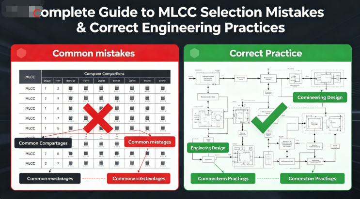
Complete Guide to MLCC Selection Mistakes & Correct Engineering Practices
mu sen Introduction
In hardware design, automotive electronic control, industrial power supplies, and high-frequency inverter projects, most MLCC failures, EMI failures, loop instability, and mass after-sales issues are NOT caused by component quality, but by early-stage selection mistakes.
Many engineers only focus on three basic parameters: package + capacitance + voltage rating, while ignoring dielectric characteristics, DC bias attenuation, temperature drift, ESR/ESL, self-resonant frequency (SRF), mechanical stress resistance, and automotive certification. This leads to seemingly correct designs that fail in prototype testing, mass production, and vehicle operation.
This article summarizes the most common MLCC selection mistakes engineers make, explains the risks, and provides the correct selection methods. It can be directly used as a hardware design specification.
1. Mistake 1: Safe to Use as Long as Working Voltage < Rated Voltage
Wrong Belief
50V or 100V MLCCs can work long-term if actual voltage does not exceed the rated value.
Real Risks
X7R/X8R dielectrics suffer 40%~70% capacitance loss at 50%~80% DC bias.
Nominal capacitance is sufficient, but actual effective capacitance drops sharply, causing filter failure, high ripple, loop oscillation, and EMI failure.
Correct Method
- Keep working voltage below 50% of rated voltage
- Use 1000V/1500V parts for 800V automotive platforms
- Reserve 30%~50% capacitance margin to compensate bias attenuation
- Use X8R low-attenuation dielectric for high DC bias applications
2. Mistake 2: X7R, X8R, Y5V Are Similar & Interchangeable
Wrong Belief
Same package and capacitance mean dielectrics can be freely replaced without performance impact.
Real Risks
- Y5V: huge temperature drift, fast aging, capacitance collapse → NOT for automotive or precision power
- X7R: acceptable for general use, but high bias attenuation and thermal aging
- X8R: stable wide temperature, low aging, low attenuation → ideal for automotive high-temperature zones
Correct Method
- Ban Y5V/Z5V in critical automotive circuits
- Use X8R for engine compartment & powertrain
- X7R only for low-voltage cockpit auxiliary circuits
- Never cross-dielectric replacement
3. Mistake 3: High-Frequency Circuits Only Need Correct Capacitance (Ignore SRF)
Wrong Belief
As long as capacitance matches, it works for high-frequency decoupling and EMI filtering.
Real Risks
MLCC is capacitive below SRF, but inductive above SRF.
For high-frequency switching, SiC/GaN, and MHz applications, insufficient SRF causes complete filter failure, severe EMI, and high voltage spikes.
Correct Method
- MLCC SRF ≥ 1.5~2 × switching frequency
- Use small packages (0201/0402) low-ESL types for high-frequency decoupling
- Combine multiple capacitances & packages to cover full frequency band
4. Mistake 4: Ignore ESR/ESL, Believing Same Capacitance = Same Performance
Wrong Belief
All 1μF 0603 MLCCs are identical; ESR/ESL do not matter.
Real Risks
- High ESR: overheating, high ripple loss, accelerated aging
- High ESL: large parasitic inductance, switching spikes, poor oscillation suppression, hard EMI fixes
Correct Method
- Use low ESR/ESL high-frequency types for power & high-frequency circuits
- Parallel multiple small capacitors to reduce total ESR/ESL
- Always check ESR vs frequency curves & SRF in datasheet
5. Mistake 5: Consumer-Grade MLCC Directly Replace AEC-Q200 Automotive Parts
Wrong Belief
Same appearance, capacitance, voltage → commercial MLCCs can replace automotive grades to save cost.
Real Risks
No AEC-Q200 certification for temperature cycling, vibration, humidity, or aging.
Unable to withstand -40℃~125℃, vibration, and long-term reliability → massive cracking, open circuit, leakage in later stage.
Correct Method
- Mandatory AEC-Q200 for powertrain, safety, engine bay
- NO downgrading to commercial parts in critical loops
- Replacement parts must match automotive grade & reliability
6. Mistake 6: Larger Packages Are More Reliable (Blindly Use 1206+)
Wrong Belief
Bigger packages = higher voltage & better stability.
Real Risks
Large packages have high rigidity and poor bending stress resistance.
Minor PCB deformation or vehicle vibration easily causes internal cracks & delamination — latent failures that pass factory tests but break in after-sales.
Correct Method
- Use small packages 0402/0603 in high-vibration & bending areas
- Parallel small caps instead of using large packages for high capacitance
- Avoid large packages near board edges, screws, connectors
7. Mistake 7: Use Standard Hard-Termination MLCC in Bending/High-Vibration Areas
Wrong Belief
Standard terminations are enough for automotive vibration; no need for flexible terminations.
Real Risks
Mechanical stress from vibration/PCB bending cannot be absorbed by hard terminations → cracking, delamination, electrode detachment.
Correct Method
- Must use flexible termination MLCCs in chassis, engine bay, motor drivers
- Design stress relief pads; avoid narrow equal-width pads
- Avoid large hard-termination parts in bending-sensitive areas
8. Mistake 8: Randomly Replace Parts by Experience Without Validation
Wrong Belief
Same spec & package = pin-to-pin replacement; no testing or curve comparison needed.
Real Risks
Ceramic formula, layer structure, bias curve, ESR/ESL vary greatly between manufacturers.
Blind replacement causes mass EMI failure, abnormal capacitance loss, and field failures.
Correct Method
- Build a qualified alternative library with pre-validation
- Must test: LCR, DC bias, temperature drift, EMI, thermal cycling before replacement
- No incomplete datasheet parts allowed in mass production
9. Mistake 9: No Temperature Derating, Operate at Full Rated Temperature
Wrong Belief
Rated 125℃ means safe for long-term 125℃ operation.
Real Risks
Long-term high temperature accelerates dielectric aging, capacitance decay, leakage increase, and shortens lifespan.
Correct Method
- Reserve ≥20℃ temperature margin
- Use 125℃+ high-grade dielectrics in engine bay
- Leave thermal relief and thermal vias near heat sources
10. Golden Rules for MLCC Selection (Direct Application)
- No cross-dielectric replacement: X7R → X8R allowed; Y5V forbidden in automotive critical circuits
- Voltage, temperature, and capacitance derating; no full-rated operation
- High-frequency designs must check SRF, ESR, ESL — not just capacitance
- Automotive powertrain & safety circuits: mandatory AEC-Q200
- High-vibration/bending areas: small package + flexible termination
- All replacements require electrical & reliability validation
- High DC bias: reserve capacitance margin, prefer X8R low-attenuation dielectric
mu sen Conclusion
MLCC selection seems simple, but involves material, structure, high-frequency parasitics, mechanical stress, temperature bias, and automotive reliability. Most engineering failures come from the common mistakes above.
Using this guide as a unified standard for hardware, layout, procurement, and quality teams eliminates 90% of MLCC failures, EMI rework, and mass after-sales risks from the source.
Dongguan Musen Leyton Electronic Technology Co., Ltd. provides a full range of AEC-Q200 automotive MLCCs, flexible termination anti-crack MLCCs, and X8R low-attenuation high-frequency MLCCs. We offer free selection support, alternative review, and engineering technical assistance.
Industrial MLCC Selection, Application Reliability Design Guide
Automotive MLCC Incoming Inspection & Mass Quality Control Practical Guide
مقالات لها صلة




