
Optimize MLCC Performance in High-Frequency Power Supplies and Motor Drives
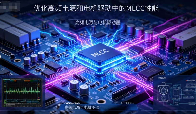
Optimize MLCC Performance in High-Frequency Power Supplies and Motor Drives
Design Guidelines & Practical Engineering Recommendations
With the continuous increase in power density of electric vehicles (EVs) and inverter systems, MLCCs play an increasingly critical role in high-frequency power filtering and direct-drive motor applications.
This article focuses on MLCC selection, PCB layout optimization, thermal management, and EMI mitigation strategies for high-frequency scenarios. It delivers actionable engineering suggestions to help R&D teams boost overall system performance while maintaining long-term product reliability.
- Component Selection: Prioritize MLCCs with low ESL, low ESR and minimal DC-bias capacitance decay; ensure self-resonant frequency matches the operating bandwidth.
- PCB Layout: Adopt multi-size capacitor parallel connection, minimize current return paths, and apply symmetric placement to reduce loop inductance and common-mode interference.
- Thermal Management: Evaluate capacitance variation caused by temperature and DC bias; design sufficient heat dissipation paths and safe temperature margin.
- Mechanical Reliability: Use crack-resistant packaging or flexible termination MLCCs in high-vibration environments; optimize pad design and reflow soldering profile.
- Validation & Testing: Conduct frequency-domain, time-domain, and thermal stress verification at both board level and system level.
1. MLCC Selection Strategy for High-Frequency Applications
Frequency Matching
Select MLCCs whose self-resonant frequency (SRF) is higher than the actual operating frequency. For wide-band filtering requirements, combine MLCCs with different package sizes and dielectric materials to fully cover low, medium and high frequency bands.
DC-Bias & Temperature Drift
For high-voltage circuits and motor direct-drive systems, choose dielectric materials with low DC-bias attenuation. Reserve 30%–50% capacitance design margin to compensate effective capacitance loss under rated voltage and long-term operating conditions.
ESR / ESL Performance
Low-ESL package designs effectively reduce parasitic inductance and improve high-frequency filtering capability. When necessary, parallel MLCCs with film capacitors to supplement low-frequency filtering performance and stabilize power loop impedance.
Reliability Grade
Adopt AEC-Q200 automotive-grade MLCCs for critical power modules and safety-related circuits. Implement 100% electrical testing or aging screening for high-reliability projects to eliminate latent defective components.
2. PCB Layout & Loop Optimization
Shortest Return Current Path
Place MLCCs as close as possible to the power and ground pins of power devices. Minimize loop area to suppress high-frequency radiation and crosstalk interference.
Multi-Capacitor Parallel Configuration
Parallel small-size MLCCs (0201 / 0402) to reduce ESL for high-frequency bypass; use large-size high-capacitance MLCCs (1206 / 1210) to enhance low-frequency energy storage and filtering effect.
Symmetric & Segmented Placement
Apply symmetric layout for multi-phase power and bridge driver structures to avoid local EMI hotspots caused by single-side current concentration.
Ground Plane & Partition Design
Adopt multi-layer complete ground planes and optimize return paths via buried vias and thermal vias. Reasonably arrange via distribution on split ground to prevent ground loop interference.
3. Thermal Control & Lifetime Management
Operating Temperature Margin
Select MLCCs with high-temperature endurance (up to 125°C or higher) according to the harsh working environment of motor drives. Reserve sufficient margin for lifetime degradation and thermal aging.
Heat Source Isolation
Avoid placing MLCCs directly above high-heat components such as bridge arms and heat sinks. Add auxiliary heat sinks or optimize air duct design if required by high-power applications.
Capacitance Decay Evaluation Under Temperature & Bias
Test actual effective capacitance under real temperature and DC-bias conditions in advance, and adjust design margin according to measured data to avoid insufficient filtering performance in extreme working conditions.
Accelerated Lifetime Verification
Perform temperature acceleration and voltage stress tests during the design validation phase to evaluate long-term service life and failure rate of MLCCs under continuous high-load operation.
4. EMI Suppression & Filter Architecture Design
Multi-Stage Filtering Structure
Adopt common-mode + differential-mode combined filtering on the input side. MLCCs undertake high-frequency bypass decoupling, while cooperating with inductors and large-capacity capacitors to achieve full-band low-frequency attenuation.
Source Impedance Matching
Evaluate the switching spectrum characteristics of power devices, reasonably adjust the Q value of the filter network, and avoid resonant peaks that cause voltage oscillation and EMI over-limit.
Routing & Shielding Design
Route sensitive signal traces away from high di/dt power loops. Add shielding layers or metal isolation structures for high-interference scenarios to improve signal integrity.
System-Level Actual Measurement & Tuning
Use oscilloscopes and spectrum analyzers to test voltage spikes, ringing noise and EMI spectral characteristics under real operating conditions. Optimize filter parameters and layout according to test results.
5. Manufacturing & Assembly Considerations
Reflow Soldering Process
Optimize the reflow profile and add a reasonable preheating stage to reduce thermal shock and internal mechanical stress. For large packages and stacked MLCCs, optimize pad structure for stress relief.
Mounting & Vibration Resistance
Reinforce component adhesion and structural fixation in high-vibration motor drive environments. Select crack-resistant MLCC packaging, and implement visual inspection and X-ray sampling inspection for solder joints.
Incoming Inspection & Traceability
Implement batch release testing for key projects, including capacitance, ESR and DC-bias characteristic verification. Preserve sample archives and full batch traceability records to support rapid failure analysis and quality closed-loop management.
6. Recommended Experimental Verification Checklist
- LCR Characteristic Test: Measure parameters at 1kHz and 1MHz; record DC-bias decay curve from 0% to 80% rated voltage.
- Time-Domain Test: Measure voltage spike and loop ringing under switching transient conditions.
- Spectrum Test: Scan EMI spectrum from 30MHz to 1GHz or higher under system full-load operation.
- Reliability Test: Complete thermal cycling, humidity resistance, vibration and accelerated lifetime tests following AEC-Q200 or enterprise internal specifications.
In high-frequency power supply and motor drive applications, MLCC electrical performance, PCB layout, thermal design and mechanical reliability are highly correlated.
By adopting scientific parallel component matching, strict current loop control, systematic EMI filtering design, standardized reliability verification and optimized assembly process, designers can significantly improve filtering performance and EMI suppression effect, while ensuring long-term stability and service life of the whole system.
Dongguan Musen Laidun Electronic Technology Co., Ltd. provides low ESR / low ESL high-frequency MLCCs, AEC-Q200 automotive-grade MLCCs and professional layout & selection technical support for inverter, new energy vehicle and industrial motor drive projects. We support free sample testing and customized reliability solutions.
Optimizing MLCC Performance in High-Frequency Power Supplies Motor Drives – Design Essentials Pra
High-Reliability MLCC Solutions for Automotive Electronics
مقالات لها صلة




