
5 Common Doubts About Electronic Components Peripherals Myths vs Facts
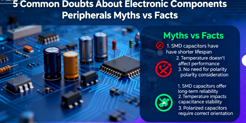
5 Common Doubts About Electronic Components Peripherals: Myths vs. Facts
Electronic components and their peripheral processes are rife with ambiguous concepts, conflicting claims, and blurred standards. From confusing ESR with ESL to misinterpreting RoHS vs. REACH compliance, these doubts plague SMT engineers, component buyers, and circuit designers—leading to wrong selection decisions, compliance risks, and production delays. The root cause often lies in overlapping technical definitions, inconsistent supplier messaging, and evolving industry standards.
1. ESR vs. ESL: What’s the Difference, and Why Do They Cause Confusion?
Equivalent Series Resistance (ESR) and Equivalent Series Inductance (ESL) are critical parameters for capacitors, inductors, and resistors—but they’re frequently mixed up. This confusion stems from overlapping terminology, misunderstood impact on circuit performance, and inconsistent documentation across suppliers.
• Myth vs. Fact: Core Definitions:
- Myth: ESR and ESL are interchangeable, measuring the same “parasitic loss” in components.
- Fact: ESR is the total resistive loss in a component (ohms), caused by electrode resistance, dielectric loss, and solder joint resistance. ESL is the parasitic inductance (nH), arising from component leads, packaging, and PCB traces.
- Key Distinction: ESR impacts low-frequency performance (e.g., power supply ripple), while ESL degrades high-frequency circuits (>1GHz, e.g., 5G modules).
• Why Confusion Persists:
- Suppliers often list “parasitic parameters” without separating ESR/ESL, especially for generic components.
- Low-quality testing equipment fails to measure ESL accurately, leading to misattributed performance issues (e.g., blaming ESR for high-frequency signal degradation).
• Practical Judgment Method:
- Use an LCR meter (Keysight E4980A) with frequency sweep (1kHz to 1GHz) to measure ESR (stable at low frequencies) and ESL (rises sharply above 100MHz).
- For high-frequency circuits, prioritize components with ESL <1nH (e.g., Murata GRM0335C1H100JW01D MLCC) and ESR <0.1Ω.
- Reference IEC 61071 standard for standardized ESR/ESL measurement protocols.
2. RoHS vs. REACH: Where’s the Boundary, and Why Do Suppliers Mislabel?
RoHS and REACH are the two most critical environmental compliance standards for electronic components, but their scope, restrictions, and applicability are often blurred. Suppliers frequently mislabel components as “RoHS/REACH compliant,” creating confusion for buyers navigating global markets.
• Clear Boundary: RoHS vs. REACH:
| Dimension | RoHS (2011/65/EU) | REACH (EC 1907/2006) |
|---|---|---|
| Core Scope | Restricts hazardous substances (Pb, Hg, Cd, etc.) in electrical/electronic equipment (EEE). | Regulates chemical substances in all products (including EEE) to protect human health/environment. |
| Restriction Type | Concentration limits (e.g., Pb ≤0.1% by weight). | Authorization list (Substances of Very High Concern, SVHC) and restriction of high-risk substances. |
| Applicability | Mandatory for EEE sold in the EU. | Mandatory for all products sold in the EU, regardless of category. |
• Why Suppliers Mislabel:
- To expand market access: Labeling non-EEE components (e.g., raw materials) as “RoHS compliant” (RoHS only applies to EEE).
- Confusing “compliant” with “free”: A component may be REACH-compliant (no SVHC) but still contain low levels of RoHS-restricted substances.
- Lack of internal testing: Suppliers rely on upstream data instead of conducting independent compliance checks.
• Compliance Verification Tips:
- Request a Declaration of Conformity (DoC) with test reports from accredited labs (e.g., TÜV, SGS).
- For RoHS, verify compliance with the latest revision (RoHS 3, 2015/863/EU) which adds 4 new restricted substances.
- For REACH, check the latest SVHC list (updated twice yearly) to ensure no prohibited substances are present.
3. MLCC vs. Tantalum Capacitors: The Reliability Controversy in High-Voltage Circuits
There’s ongoing debate about whether MLCCs (Multi-Layer Ceramic Capacitors) or tantalum capacitors are more reliable in high-voltage circuits (>50V). This controversy arises from conflicting failure modes, application-specific performance, and biased supplier claims.
• Myth vs. Fact: Reliability Realities:
- Myth 1: Tantalum capacitors are always more reliable in high voltage—they don’t suffer from “voltage derating.”
- Fact 1: Tantalum capacitors are prone to thermal runaway under overvoltage (>1.2x rated value), causing short circuits. They require voltage derating (use 50% of rated voltage) in high-voltage applications.
- Myth 2: MLCCs are unstable in high voltage due to capacitance drift.
- Fact 2: High-voltage MLCCs (e.g., X7R, C0G) with voltage ratings ≥100V have minimal drift (±15% for X7R) and no thermal runaway risk—ideal for pulsed high-voltage circuits.
• Key Controversy Drivers:
- Application mismatch: Tantalum capacitors excel in low-ESR, high-capacitance high-voltage circuits (e.g., industrial power supplies), while MLCCs perform better in high-frequency, pulsed high-voltage circuits (e.g., RF transmitters).
- Failure mode perception: MLCC failures (dielectric breakdown) are often visible, while tantalum thermal runaway is catastrophic—leading to biased reliability assessments.
- Keyword Note: “MLCC vs tantalum capacitors reliability controversy” targets engineers searching for unbiased comparisons—this section directly addresses their intent.
• Practical Selection Guide:
- Choose MLCCs (e.g., TDK CGA5E3X7R1H106K, 50V) for high-frequency, pulsed high-voltage circuits—no thermal runaway risk, low ESL.
- Opt for tantalum capacitors (e.g., Kemet T491A106K016AT, 16V) only in low-ripple, derated high-voltage circuits—high capacitance in compact packages.
- For critical applications (e.g., medical devices), use redundant design (parallel MLCC + tantalum) to mitigate failure risks.
• Case Study: An industrial power supply manufacturer resolved reliability issues by switching from tantalum to high-voltage MLCCs—thermal runaway failures dropped to zero, and capacitance stability improved by 30%.
4. ESD Testing Levels: Ambiguity in Standards and Use Case Application
ESD (Electrostatic Discharge) testing levels for electronic components are ambiguous—different standards (ANSI/ESD S20.20, IEC 61000-4-2) define varying voltage levels, and engineers struggle to determine which standard applies to their use case. This ambiguity leads to over-testing (increased costs) or under-testing (hidden damage risks).
• Core Ambiguities Explained:
- Standard Conflicts: ANSI/ESD S20.20 classifies components as “sensitive” (<2kV) or “insensitive” (>8kV), while IEC 61000-4-2 defines test levels from 2kV (contact) to 8kV (air) for EEE.
- Use Case Ambiguity: There’s no clear guidance on whether to use contact or air discharge for different components (e.g., diodes vs. ICs) or assembly stages (storage vs. production).
- Supplier Inconsistency: Suppliers often specify “ESD compliant” without citing the standard or test level—providing no actionable data.
• Clarified Testing Framework:
By Component Type:
- Sensitive components (ICs, diodes): Test to IEC 61000-4-2, 2kV contact discharge / 4kV air discharge.
- Robust components (capacitors, resistors): Test to ANSI/ESD S20.20, 4kV contact discharge / 8kV air discharge.
By Assembly Stage:
- Storage/transport: Use ANSI/ESD S20.20 (focus on protection products like trays/gloves).
- Production/testing: Use IEC 61000-4-2 (focus on component resilience during handling).
Reference IPC-A-610 for standardized ESD testing documentation in SMT assembly.
• How to Avoid Ambiguity:
- Specify the exact standard and test level in component purchase orders (e.g., “IEC 61000-4-2, 2kV contact discharge”).
- Use calibrated ESD test equipment (e.g., Desco 40600) to verify supplier claims.
- Document ESD testing protocols per ISO 9001 to ensure consistency across production.
5. Same MSL Grade, Different Moisture Sensitivity: What’s the Hidden Factor?
Electronic components with the same MSL (Moisture Sensitivity Level) often exhibit different moisture sensitivity performances—some absorb moisture faster, leading to reflow soldering failures (popcorning, delamination). This inconsistency confuses buyers and raises doubts about MSL’s reliability as a specification.
• Root Cause of the Discrepancy:
- Packaging Quality: MSL only defines moisture absorption limits, not packaging effectiveness. Generic moisture barrier bags (MBBs) with poor sealing (MVTR >0.01g/100in²/24h) allow faster moisture penetration than premium bags (e.g., 3M Moisture Shield Bags).
- Dielectric/Encapsulation Material: Polymer capacitors absorb more moisture than ceramic ones, even at the same MSL (e.g., MSL 3 polymer vs. MSL 3 MLCC).
- Manufacturing Variability: Minor differences in component encapsulation (e.g., epoxy thickness) affect moisture ingress—suppliers with stricter quality control have more consistent performance.
- Storage Conditions Post-Manufacture: Components may be exposed to high humidity (>60% RH) during shipping, even if MSL-compliant at the factory.
• Myth vs. Fact About MSL:
- Myth: Same MSL = same moisture sensitivity—no need to adjust storage/handling.
- Fact: MSL is a minimum standard, not a performance guarantee. Additional precautions are needed for moisture-prone components (polymers, ICs) with the same MSL as ceramic components.
• Practical Mitigation Strategies:
- Prioritize components with premium packaging (hermetic MBBs + desiccants + humidity indicators) regardless of MSL.
- For polymer/IC components (MSL 3-6), pre-bake at 125°C for 24 hours before reflow—even if within the 168-hour exposure window (J-STD-033).
- Store MSL 3+ components in controlled environments (20-25°C, 30-60% RH) and track exposure time from packaging opening.
- Audit suppliers’ packaging processes to ensure compliance with IPC/JEDEC J-STD-033.
• Case Study: A consumer electronics factory reduced popcorning failures by 80% by pre-baking MSL 3 polymer capacitors—even though they were stored within standard conditions, hidden moisture absorption caused failures during reflow.
Final Thoughts
The most common doubts about electronic components peripherals stem from ambiguous standards, conflicting supplier claims, and misunderstood technical parameters. By separating myths from facts, referencing industry standards (IEC, ANSI, IPC), and applying practical judgment methods, you can make informed decisions, reduce compliance risks, and optimize production reliability.
5 Most Common Faults with Chip Capacitor Peripheral Products Fixes for Mass Production
5 Top Issues with Electronic Components Peripheral Products Solutions for Mass Production
Article associé




