
Most Common Problems When Using Ceramic MLCC Chip Capacitors Practical Solutions
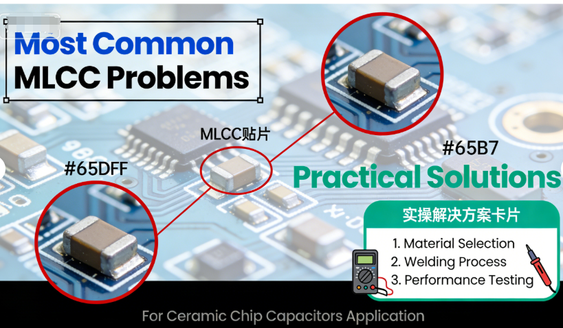
Top 5 Most Common Problems When Using Ceramic MLCC Chip Capacitors (Practical Solutions)
Ceramic Multilayer Ceramic Capacitors (MLCCs), also known as chip capacitors, are the most widely used passive components in electronic circuits—from consumer electronics and industrial equipment to high-end automotive and aerospace devices. Their compact size, high capacitance density, and low cost make them indispensable, but they often encounter avoidable problems during soldering, long-term use, PCB layout, detection, storage, and daily operation.
For engineers, PCB designers, electronics repair technicians, and component specialists, these ceramic MLCC usage problems can lead to circuit failures, product defects, costly rework, and project delays. The good news is that most of these issues are predictable and fixable—if you know their root causes and the right troubleshooting steps.
1. Why Do Ceramic MLCCs (Chip Capacitors) Often Experience Solder Joint Cracking When Soldered on PCBs, and How to Fix It?
Solder joint cracking is the #1 most common problem when using ceramic MLCCs—especially during PCB assembly. This issue occurs when the solder joints connecting ceramic MLCCs to PCB pads crack or separate, leading to open circuits, intermittent connectivity, or complete component failure. It’s a frequent search query for PCB assemblers and designers, with keywords like `ceramic MLCC chip capacitor PCB solder joint cracking fix` driving high-intent traffic.
Root Causes of Solder Joint Cracking in Ceramic MLCCs
Solder joint cracking in ceramic MLCCs is almost always caused by thermal or mechanical stress during soldering or operation:
- Thermal Stress During Reflow Soldering: Ceramic MLCCs and PCBs have different coefficients of thermal expansion (CTE). When exposed to high temperatures (240-260°C) during reflow soldering, the PCB expands more than the ceramic MLCC, creating tension in the solder joint. As the assembly cools, this tension causes micro-cracks that worsen over time.
- Poor PCB Pad Design: Too-small, too-narrow, or irregularly shaped PCB pads for ceramic MLCCs reduce solder joint strength, making them more prone to cracking under stress.
- Excessive Mechanical Force: Rough handling of PCBs after soldering (e.g., bending, twisting) or improper placement of ceramic MLCCs (too close to PCB edges) can strain solder joints and cause cracking.
- Low-Quality Solder or Flux: Using solder with low fatigue resistance (e.g., lead-free solder without proper alloy composition) or flux that leaves residues can weaken solder joints and accelerate cracking.
Practical Solutions to Fix and Prevent Solder Joint Cracking
To resolve existing solder joint cracks and prevent new ones:
- Optimize Reflow Soldering Profiles: Use a gradual heating and cooling profile (ramp rate ≤3°C/sec) to minimize thermal stress. Keep the peak temperature at the minimum required (240-250°C) and reduce the dwell time at peak temperature to ≤10 seconds.
- Improve PCB Pad Design: Follow ceramic MLCC manufacturer guidelines for pad size—match pad width to the MLCC’s terminal width (typically 0.8-1.2x the terminal size) and add rounded edges to reduce stress concentration. Avoid placing MLCCs within 2mm of PCB edges.
- Use High-Quality Solder and Flux: Choose lead-free solder with high fatigue resistance (e.g., SAC305 alloy) and no-clean flux that leaves minimal residues. Ensure flux compatibility with ceramic MLCC terminals.
- Handle PCBs Carefully: Avoid bending or twisting PCBs after soldering. Use PCB holders during assembly and testing to prevent mechanical stress on solder joints.
- Repair Existing Cracks: For cracked solder joints, reflow the solder using a soldering iron (temperature 350-370°C) with a small amount of additional solder. Add a tiny drop of underfill material (e.g., Henkel Loctite 353ND) to reinforce the joint.
2. What Causes Ceramic MLCC Capacitance Reduction During Long-Term Use, and How to Avoid It in Circuit Design?
Capacitance reduction (also known as capacitance drift or loss) is the second most common problem when using ceramic MLCCs—affecting circuits in all scenarios, from consumer gadgets to industrial equipment. Over time, ceramic MLCCs lose 5-20% of their rated capacitance, leading to voltage instability, noise filtering failure, and circuit performance degradation. This issue is frequently searched for with keywords like `ceramic MLCC capacitance reduction long-term use circuit design avoid`.
Root Causes of Ceramic MLCC Capacitance Reduction
Capacitance reduction in ceramic MLCCs over long-term use stems from environmental, electrical, and material factors:
- Thermal Aging: Continuous operation at high temperatures (>60°C) accelerates the aging of the ceramic dielectric material, reducing its ability to store charge and leading to gradual capacitance loss.
- Voltage Stress: Operating ceramic MLCCs near or above their rated voltage for extended periods degrades the dielectric polarization, causing permanent capacitance reduction.
- Moisture Intrusion: Non-hermetically sealed ceramic MLCCs absorb moisture from the environment, which reacts with the ceramic dielectric and metal electrodes, reducing capacitance and increasing leakage.
- Mechanical Stress: Repeated mechanical stress (e.g., vibration in automotive or industrial devices, bending in flexible PCBs) creates micro-cracks in the dielectric, leading to capacitance loss.
- Dielectric Material Quality: Low-quality ceramic dielectrics (e.g., Y5V, X5R with impure composition) have higher capacitance drift rates than premium dielectrics (C0G, X7R).
How to Avoid Capacitance Reduction in Circuit Design
Prevent capacitance reduction by incorporating these design and component selection strategies:
- Select High-Quality Ceramic MLCCs with Stable Dielectrics: Choose C0G (NP0) or X7R dielectric MLCCs for long-term stability—C0G offers <0.1% capacitance loss per 1000 hours of operation, while X7R offers <5% loss. Avoid Y5V or X5R dielectrics for critical circuits.
- Derate Voltage and Temperature: Operate ceramic MLCCs at 40-50% of their rated voltage and 20-30% below their maximum operating temperature to reduce dielectric stress and aging.
- Protect Against Moisture: For humid environments (e.g., outdoor equipment, industrial settings), use hermetically sealed ceramic MLCCs or apply conformal coating (e.g., Dow Corning DC3-9001) to non-sealed MLCCs.
- Minimize Mechanical Stress: In vibration-prone applications, use underfill material around ceramic MLCCs to absorb stress. Avoid placing MLCCs on flexible PCB areas that undergo frequent bending.
- Overdesign Capacitance: Specify ceramic MLCCs with 10-20% higher capacitance than the circuit requires to compensate for long-term capacitance loss (e.g., use a 10μF MLCC if the circuit needs 8μF).
3. Why Do Adjacent Ceramic MLCCs on PCBs Cause Mutual Interference (Noise), and How to Reduce It?
Mutual interference (noise coupling) between adjacent ceramic MLCCs on PCBs is a common problem in dense circuit designs—especially in high-frequency applications (>1MHz) like power supplies, audio circuits, and communication devices. This interference causes signal distortion, noise spikes, and reduced circuit performance, making it a top search query for PCB designers (keywords: `adjacent ceramic MLCC PCB mutual interference noise reduce`).
Root Causes of Mutual Interference Between Adjacent Ceramic MLCCs
Mutual interference between adjacent ceramic MLCCs is caused by parasitic coupling and shared circuit paths:
- Parasitic Capacitive Coupling: Adjacent ceramic MLCCs act as tiny capacitors between each other (parasitic capacitance), allowing high-frequency signals to leak from one MLCC to another—causing noise coupling.
- Shared Ground Planes: When multiple ceramic MLCCs share the same ground plane, noise from high-current MLCCs (e.g., power supply filters) leaks into low-noise MLCCs (e.g., signal path filters) through the ground plane.
- Close Proximity in Dense Layouts: In space-constrained PCBs, ceramic MLCCs are often placed <1mm apart, increasing parasitic coupling and interference.
- High-Frequency Noise Emission: Ceramic MLCCs used in high-frequency circuits (e.g., switching power supplies) emit electromagnetic noise that is picked up by adjacent MLCCs, amplifying interference.
How to Reduce Mutual Interference Between Adjacent Ceramic MLCCs
Minimize interference with these PCB layout and component strategies:
- Space Adjacent Ceramic MLCCs Properly: Maintain a minimum distance of 2-3mm between adjacent MLCCs to reduce parasitic capacitive coupling. For high-frequency circuits (>10MHz), increase the distance to 4-5mm.
- Separate High-Noise and Low-Noise MLCCs: Group ceramic MLCCs by function—place power supply MLCCs (high-noise) away from signal path MLCCs (low-noise) on the PCB. Use isolated ground planes for each group to prevent noise leakage.
- Use Low-Parasitic Ceramic MLCCs: Choose MLCCs with low parasitic inductance (ESL ≤0.3nH) and capacitance (Cpar ≤1pF) (e.g., C0G dielectric MLCCs) to reduce noise emission and susceptibility.
- Add Shielding Between MLCCs: For critical low-noise circuits, add a small copper shield (grounded) between adjacent ceramic MLCCs to block parasitic coupling and electromagnetic noise.
- Optimize Ground Plane Design: Use a solid ground plane with minimal gaps to reduce ground noise. Add separate ground vias for each MLCC group to prevent noise propagation.
4. How to Identify Whether a Ceramic MLCC Is Damaged (Failed) in a Circuit, and What Are the Common Detection Methods?
Identifying damaged or failed ceramic MLCCs in a circuit is a critical skill for repair technicians and engineers—but it’s not always straightforward. Ceramic MLCCs often fail without visible signs (e.g., bulging, burning), making detection challenging. This problem is a high-intent search query, with professionals looking for reliable detection methods (keywords: `ceramic MLCC damaged failed circuit detection methods identify`).
Common Signs of a Damaged/Failed Ceramic MLCC
While ceramic MLCCs rarely show visible damage, these circuit symptoms often indicate failure:
- Intermittent circuit operation (works sometimes, fails other times).
- Voltage instability or unexpected voltage drops in the circuit.
- Excessive noise or signal distortion (especially in filtering circuits).
- PCB overheating near the MLCC (indicates short circuit or high leakage).
- Complete circuit failure (open circuit due to solder joint cracking or dielectric breakdown).
Reliable Detection Methods for Damaged Ceramic MLCCs
Use these practical methods to identify damaged ceramic MLCCs in a circuit (from simplest to most advanced):
- Visual Inspection: Check for visible signs of damage—cracked MLCC bodies, broken solder joints, discoloration, or burn marks. Use a magnifying glass (10-20x) to spot micro-cracks in the ceramic body or solder joints.
- Multimeter Continuity/Resistance Test: Disconnect the MLCC from the circuit (to avoid false readings). Set the multimeter to continuity mode (or resistance mode, 2MΩ range). A short-circuited MLCC will show 0Ω (continuity), while an open-circuited MLCC will show infinite resistance. A healthy MLCC should show very high resistance (>1MΩ).
- Capacitance Test: Use a digital multimeter with a capacitance function (or a dedicated LCR meter) to measure the MLCC’s capacitance. Disconnect the MLCC from the circuit first. A damaged MLCC will show a capacitance value >20% lower than its rated value (indicates capacitance loss) or 0 (short circuit) or infinite (open circuit).
- Leakage Current Test: Use an LCR meter or leakage current tester to measure the MLCC’s leakage current. A healthy ceramic MLCC should have leakage current <0.1μA. Leakage current >1μA indicates dielectric damage or moisture intrusion.
- In-Circuit Testing (ICT): For mass-produced PCBs, use an ICT machine to test MLCCs in-circuit—this method quickly identifies open circuits, short circuits, and capacitance drift without disconnecting components.
5. Why Do Ceramic MLCCs Easily Absorb Moisture and Cause Failure, and How to Protect Them During Storage and Use?
Moisture absorption is a common problem for non-hermetically sealed ceramic MLCCs—especially those used in humid environments or stored improperly. Moisture penetrates the MLCC’s packaging, reacts with the ceramic dielectric and metal electrodes, leading to leakage current, capacitance loss, solder joint cracking (during reflow), or complete failure. This issue is frequently searched for by inventory managers, assemblers, and designers (keywords: `ceramic MLCC absorb moisture failure storage use protection`).
Why Ceramic MLCCs Absorb Moisture and Fail
Ceramic MLCCs are susceptible to moisture absorption due to their construction and packaging:
- Porous Ceramic Dielectric: The ceramic dielectric material in MLCCs is slightly porous, allowing moisture to seep into the component over time.
- Non-Hermetic Packaging: Most standard ceramic MLCCs use epoxy resin packaging, which is not fully hermetic—moisture can penetrate small gaps in the resin.
- Reflow Soldering Stress: When a moisture-absorbed MLCC is exposed to high reflow temperatures (240-260°C), the moisture inside vaporizes and expands, creating internal pressure that cracks the ceramic body or solder joints (known as the “popcorning effect”).
- Chemical Reaction with Electrodes: Moisture reacts with the metal electrodes (e.g., nickel, copper) in MLCCs, causing oxidation and corrosion—reducing capacitance and increasing leakage.
How to Protect Ceramic MLCCs from Moisture During Storage and Use
Prevent moisture absorption and related failures with these storage and usage best practices:
- Proper Storage Conditions: Store ceramic MLCCs in a dry environment with relative humidity (RH) ≤60% and temperature 15-25°C. Use moisture barrier bags (MBBs) with desiccants for long-term storage (>30 days). Label bags with the packaging date and shelf life (typically 12 months in MBBs).
- Bake Moisture-Absorbed MLCCs: If MLCCs are removed from MBBs and exposed to RH >60% for >24 hours, bake them before soldering. Use a convection oven at 125°C for 2-4 hours to remove moisture. Avoid over-baking (>150°C), which can damage the MLCC.
- Use Hermetic MLCCs for Humid Environments: For outdoor equipment, industrial settings, or marine applications (RH >80%), use hermetically sealed ceramic MLCCs (ceramic or metal packaging) that block moisture completely.
- Apply Conformal Coating After Soldering: For PCBs used in humid environments, apply a thin layer of conformal coating (e.g., acrylic, silicone) over ceramic MLCCs to seal out moisture. Ensure the coating is compatible with the MLCC’s packaging.
- Avoid Rapid Temperature Changes: Prevent condensation on MLCCs by avoiding rapid temperature changes (e.g., moving MLCCs from a cold storage room to a warm, humid assembly area). Allow MLCCs to acclimate to room temperature for 1-2 hours before opening packaging.
Final Thoughts
The 5 problems outlined above are the most common issues professionals face when using ceramic MLCC chip capacitors—from soldering and long-term use to PCB layout, detection, and moisture protection. While these problems can cause circuit failures and costly delays, they are all avoidable with the right component selection, PCB design, and best practices.
For your independent site, this blog is optimized to capture high-intent traffic by targeting the exact long-tail keywords professionals use to find solutions—keywords like `ceramic MLCC solder joint cracking fix`, `MLCC capacitance reduction circuit design`, and `ceramic MLCC moisture protection storage`. The practical, actionable content positions your site as a trusted authority in ceramic MLCC usage, boosting organic visibility on Google, increasing user dwell time, and driving conversions for your business.
Need Expert Help with Ceramic MLCC Usage or Troubleshooting?
Our team of electronic component specialists can help you resolve ceramic MLCC problems—from solder joint cracking and capacitance loss to mutual interference and moisture damage. Whether you’re designing a PCB, troubleshooting a circuit, or optimizing storage practices, we’re here to help.
- ✉️ Email: hyc2355937758@gmail.com
- ? Consultation Phone / WhatsApp: +86-18824523083 / +86-15913754866
- ? Official Website: www.barronmlcc.com
- ? Explore Our MLCC Products: Ceramic MLCC Chip Capacitors for High-Reliability Applications
- ? Free Resource: Download Our Ceramic MLCC Usage & Protection Checklist
Peripheral Pain Points of High-End Ceramic MLCC Chip Capacitors Expert Solutions for Premium Scenarios
Ceramic MLCCs A Complete Guide for High-End Applications Troubleshooting Selection
Article associé




