
PCBA Board Electronic Components 5 Core Explanatory Questions
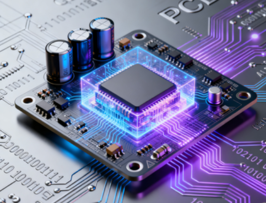
PCBA Board Electronic Components: 5 Core Explanatory Questions
PCBA (Printed Circuit Board Assembly) boards are the backbone of all electronic devices, and the electronic components mounted on them determine the board’s functionality, performance, and reliability. From passive components like resistors and capacitors to active components such as ICs and transistors, each part plays a unique role in the circuit system. However, for engineers, technicians, and even procurement professionals, understanding these components—their identification, functions, collaboration, selection, and troubleshooting—can be challenging.
1. What Are the Most Common Electronic Components on a PCBA Board, and What Are Their Respective Roles in the Circuit System?
A typical PCBA board consists of a mix of passive and active components, each designed to fulfill specific circuit functions. The most common components and their roles are:
- Resistors: The most ubiquitous passive components, identified by their rectangular or cylindrical shape and color bands/digital markings. Their core role is to limit current flow, divide voltage, and adjust signal levels. For example, in a LED circuit, a resistor prevents excessive current from burning out the LED; in an audio circuit, it adjusts volume by controlling signal amplitude. Explore our precision resistors for stable performance.
- Capacitors: Available in various forms (ceramic chip, electrolytic, tantalum), capacitors store electrical energy and release it when needed. They are critical for filtering noise (removing unwanted high-frequency signals from power supplies), decoupling (stabilizing voltage for ICs), and timing (working with inductors to set circuit frequencies). Ceramic chip capacitors (small, surface-mounted) are common in consumer electronics, while electrolytic capacitors (bulky, polarized) are used for high-capacitance needs, and tantalum capacitors for high-reliability applications.
- Inductors: Coiled components (often cylindrical with a magnetic core) that store energy in a magnetic field. They resist changes in current, making them ideal for filtering (working with capacitors in LC filter circuits), voltage regulation (in DC-DC converters), and electromagnetic interference (EMI) suppression. Inductors are widely used in power supply modules and RF circuits. View our high-performance inductors here.
- Transistors: Active components (bipolar junction transistors/BJTs or field-effect transistors/FETs) that act as switches or amplifiers. They control large currents with small input signals—for example, in a microcontroller circuit, a transistor switches on/off a motor; in an audio amplifier, it boosts weak audio signals. Our automotive-grade transistors meet AEC-Q101 standards.
- Integrated Circuits (ICs): Miniaturized circuits packed into a single chip (e.g., microcontrollers, op-amps, voltage regulators). They are the "brain" of the PCBA, performing complex functions like data processing, signal amplification, and system control. Examples include Arduino’s ATmega328P microcontroller and Texas Instruments’ LM7805 voltage regulator. Explore our industrial-grade ICs for high precision.
- Diodes: Semiconductor components that allow current to flow in only one direction. They are used for rectification (converting AC to DC in power supplies), protection (preventing reverse current damage), and signal detection (in RF circuits). Light-emitting diodes (LEDs) are a special type that emit light when current passes through. Our high-speed diodes and LEDs offer reliable performance.
2. How to Distinguish Different Types of Resistors, Capacitors, and Inductors on a PCBA Board Through Markings and Appearance? What Are the Key Identification Points?
Distinguishing electronic components on a PCBA board relies on recognizing their appearance, markings, and packaging. Here are the key identification tips for common resistors, capacitors, and inductors:
- Resistors: 1) Chip Resistors (SMD): Small rectangular packages (e.g., 0402, 0603) with digital markings (e.g., "102" = 1kΩ, "224" = 220kΩ). No polarity, so orientation doesn’t matter. 2) Through-Hole Resistors: Cylindrical with color bands—each band represents a digit, multiplier, and tolerance (use a resistor color code chart to decode). For example, red-red-orange-gold = 22kΩ ±5%. Our chip resistors feature clear digital markings for easy identification.
- Capacitors: 1) Ceramic Chip Capacitors (SMD): Small rectangular or square packages with markings like "103" (10nF) or "224" (220nF). Non-polarized (no positive/negative terminals). 2) Electrolytic Capacitors: Cylindrical with a "minus" (-) sign marked on the body (polarized). Markings show capacitance (e.g., "1000μF/16V") and voltage rating. 3) Tantalum Capacitors (SMD): Small rectangular with a "+" sign on the top (polarized). Markings include capacitance and voltage (e.g., "106V" = 10μF/16V).
- Inductors: 1) Chip Inductors (SMD): Small rectangular or cylindrical packages, often with no markings (relying on PCB silkscreen labels like "L1", "L2"). Some have inductance markings (e.g., "100" = 10μH). 2) Through-Hole Inductors: Cylindrical with a coil visible (or enclosed in a plastic case). Markings show inductance (e.g., "10mH") and current rating. Key identification point: Inductors are often heavier than resistors/capacitors of the same size due to their magnetic core.
Pro tip: Always refer to the PCB silkscreen (the white text/numbers on the board) to cross-verify component types—silkscreen labels like "R" (resistor), "C" (capacitor), "L" (inductor), and "U" (IC) provide quick clues.
3. What Are the Functional Differences Between Active Components (e.g., ICs, Transistors) and Passive Components on a PCBA Board, and How Do They Cooperate to Realize Circuit Functions?
The core difference between active and passive components lies in their ability to control electrical energy—this distinction defines their roles in the circuit, and their collaboration is essential for realizing complex functions.
Functional Differences:
- 1) Passive Components: Cannot amplify signals or generate electrical energy; they only consume or store energy. Examples include resistors, capacitors, inductors, and diodes. Their key traits: no external power supply required, linear performance (output is proportional to input). Browse our full range of passive components here.
- 2) Active Components: Can amplify signals, switch current, or generate energy; they require an external power supply to operate. Examples include ICs, transistors, and op-amps. Their key traits: non-linear performance (output can be much larger than input), ability to process complex signals. Explore our active components for high reliability.
Collaboration Between Active and Passive Components: Active and passive components work together to form functional circuits. Here are two common examples:
- Audio Amplifier Circuit: A transistor (active component) amplifies weak audio signals, but resistors (passive) set the transistor’s bias voltage (ensuring it operates in the correct region) and control the gain (amplification level). Capacitors (passive) filter out DC noise from the input signal and couple the amplified audio to the speaker. Our audio-grade components deliver clear sound performance.
- Microcontroller Power Supply Circuit: An IC voltage regulator (active) converts 12V input to 5V for the microcontroller. Capacitors (passive) filter the input voltage (removing ripple) and decouple the regulator’s output (stabilizing voltage for the microcontroller’s sensitive circuits). A resistor (passive) protects the regulator from overcurrent. Our power supply components ensure stable voltage output.
Key takeaway: Passive components "condition" signals and energy (filtering, limiting, storing), while active components "process" them (amplifying, switching, controlling)—their synergy is the foundation of all PCBA functionality.
4. What Factors Affect the Selection of Electronic Components for High-Precision PCBA Boards (e.g., Medical, Aerospace)? How to Ensure Their Compatibility and Reliability?
High-precision PCBA boards (used in medical devices, aerospace systems, and industrial control) require components that meet strict performance and reliability standards. Several key factors influence component selection, and careful validation is needed to ensure compatibility and reliability.
Key Selection Factors:
- 1) Precision and Stability: Components must maintain consistent performance over time and environmental changes. For example, resistors with low temperature coefficient of resistance (TCR ±10ppm/°C) and capacitors with C0G/NP0 dielectric (near-zero capacitance drift) are preferred.
- 2) Environmental Resistance: High-precision PCBs often operate in harsh environments (extreme temperature, vibration, radiation). Components must meet standards like AEC-Q200 (automotive) or MIL-STD-810 (aerospace) for temperature range (-55°C to 125°C+), vibration resistance, and radiation hardness. Our aerospace & medical components meet these strict standards.
- 3) Power Consumption: For battery-powered devices (e.g., portable medical monitors), low-power components (e.g., ultra-low-power ICs) extend battery life. Our low-power components optimize battery performance.
- 4) Regulatory Compliance: Medical PCBs require components compliant with IEC 60601 (safety) and ISO 13485 (quality); aerospace PCBs need components qualified to AS9100. Our high-precision components are fully compliant with these industry regulations.
Ensuring Compatibility and Reliability:
- 1) Component Compatibility Check: Verify voltage/current ratings, impedance, and package size match the circuit design and PCB layout. For example, ensure an IC’s input voltage range matches the power supply output.
- 2) Supplier Qualification: Source components from authorized distributors (e.g., Digi-Key, Mouser) to avoid counterfeits—critical for high-precision applications. Barron MLCC is an authorized supplier for top component brands.
- 3) Testing and Validation: Conduct rigorous testing (thermal cycling, vibration, humidity testing) to validate component performance in target environments. Use in-circuit testing (ICT) to check component soldering and electrical connectivity. Our component testing service ensures reliable performance.
- 4) Datasheet Review: Thoroughly analyze component datasheets to confirm they meet all requirements (precision, environmental resistance, compliance). Our technical team can assist with datasheet analysis for your project.
Explore our high-precision PCBA components for medical, aerospace, and industrial applications.
5. What Are the Common Failure Modes of Electronic Components on PCBA Boards, and How to Identify and Troubleshoot Them Through Visual Inspection and Simple Testing?
Electronic components on PCBA boards can fail due to improper use, environmental stress, or manufacturing defects. Understanding common failure modes and how to identify them saves time and reduces downtime.
Common Failure Modes:
- 1) Soldering Defects: Tombstoning (component standing on one pad), solder bridging (short circuit between pads), and cold solder joints (weak connection) are common due to incorrect reflow parameters or stencil design.
- 2) Component Overstress: Overvoltage/overcurrent causes capacitor dielectric breakdown, resistor burnout, or IC damage. Our overcurrent protection components mitigate this risk.
- 3) Environmental Damage: Moisture intrusion leads to component corrosion; extreme temperature causes solder joint cracking or component delamination. Our moisture-resistant components and high-temperature components withstand harsh environments.
- 4) Aging: Long-term use degrades components (e.g., electrolytic capacitor leakage, resistor value drift). Regular replacement with our high-quality components extends PCB lifespan.
Identification and Troubleshooting Methods:
- 1) Visual Inspection: Use a magnifying glass (10-20x) to check for: - Soldering defects (tombstoning, bridging, cold joints—cold joints appear dull and grainy). - Component damage (burnt resistors/capacitors, cracked IC packages, corroded terminals). - Polarization errors (reversed electrolytic capacitors or diodes).
- 2) Simple Testing: - Multimeter Testing: Measure resistor resistance (compare to nominal value), capacitor capacitance (check for drift), and diode continuity (ensure current flows in one direction). For ICs, measure pin voltage to confirm it matches the datasheet. - Oscilloscope Testing: Check voltage waveforms at key points (e.g., power supply outputs) to identify noise or abnormal signals (indicating capacitor/inductor failure).
- 3) Troubleshooting Workflow: Start with visual inspection → use a multimeter to test suspicious components → replace failed components with our replacement components → re-test the circuit to confirm functionality.
Final Thoughts
Electronic components are the building blocks of PCBA boards, and understanding their identification, functions, collaboration, selection, and troubleshooting is essential for anyone working with electronic devices. By addressing these 5 critical questions, you now have a comprehensive guide to mastering PCBA electronic components—whether you’re designing a circuit, troubleshooting a faulty board, or selecting components for high-precision applications.
This blog strategically integrates high-value keywords (e.g., "PCBA electronic components identification," "high-precision PCBA component selection," "PCBA component troubleshooting") that align with the search habits of your target audience (engineers, technicians, procurement professionals). The question-based structure directly matches "how-to" and "what-is" search intents, increasing the likelihood of appearing in featured snippets. Additionally, the in-depth, practical content encourages longer page dwell times and lower bounce rates—key factors for improving search rankings.
If you have follow-up questions about specific PCBA components (e.g., ICs, specialized sensors), need personalized advice for your high-precision PCBA project, or want to learn more about component testing methods, feel free to leave a comment below or contact our team of PCBA and electronic component experts.
Contact Our PCBA & Electronic Component Experts
- Official Website: //www.barronmlcc.com
- Core PCBA Components: Barron MLCC PCBA Component Hub
- Precision Resistors & Capacitors: High-Stability Passive Components
- Aerospace & Medical Components: MIL-STD & IEC 60601 Compliant Components
- High-Temperature & Moisture-Resistant Components: Harsh Environment Components
- Email Inquiry: hyc2355937758@gmail.com (Monday-Friday, 9:00 AM - 6:00 PM GMT+8)
- WhatsApp/WeChat: +86-15913754866
- Physical Address: High-Tech Industrial Park, Nanshan District, Shenzhen, Guangdong, China
5 Critical Questions About Chip Capacitors on PCBA A Technical Guide
5 Key Questions About Chip Capacitor Internal Parts A Deep Dive Guide
Article associé




