
High-Reliability MLCC Application in Industrial Control Automation Strong EMC Protection Wide Temperature Stability 10-Year Long-Life Design Full-Scenario Selection Solutions
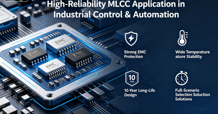
High-Reliability MLCC Application in Industrial Control & Automation: Strong EMC Protection, Wide Temperature Stability, 10-Year Long-Life Design & Full-Scenario Selection Solutions
Company: Dongguan Musen Laidun Electronic Technology Co., Ltd.
Industrial Control MLCC, PLC Capacitor, Frequency Converter Capacitor, Industrial Automation Capacitor, Anti-Interference MLCC, Strong EMC Capacitor, Wide Temperature Industrial Capacitor, Anti-Corrosion Industrial Capacitor
mu sen Introduction
The comprehensive advancement of Industry 4.0 and intelligent manufacturing is driving industrial control and automation systems toward higher precision, higher integration, and greater intelligence. Core equipment such as PLC (Programmable Logic Controller), frequency converters, servo drives, industrial sensors, and industrial switches constitute the nerve center of modern industrial automation. As the most widely used passive component in industrial control equipment, MLCC usage exceeds 500 units per high-end PLC and 1000 units per high-power frequency converter. It is extensively deployed in core circuits such as power filtering, signal conditioning, decoupling, coupling, and surge suppression, making it the key component determining the stability, reliability, and anti-interference capability of industrial control systems.
Industrial site environments are extremely harsh, with multiple adverse factors including strong electromagnetic interference, voltage fluctuations, high/low temperature alternations, vibration shocks, dust and humidity, and corrosive gases. Industrial control equipment requires 7×24 uninterrupted operation, design life ≥10 years, and Mean Time Between Failures (MTBF) ≥100,000 hours. Any failure can lead to production line shutdowns and huge economic losses. Ordinary consumer-grade and even general industrial-grade MLCC cannot adapt to such harsh working conditions, commonly suffering from malfunctions caused by electromagnetic interference, high-temperature aging failure, surge breakdown, and corrosion open circuit. According to industry statistics, over 45% of electrical faults and more than 60% of intermittent faults in industrial control equipment are related to improper MLCC selection and design.
Based on IEC 61131, GB/T 15969, IEC 61000 electromagnetic compatibility standards, combined with design specifications from global mainstream industrial automation manufacturers, this whitepaper systematically disassembles the special requirements of industrial control and automation for MLCC, deeply analyzes core failure mechanisms in industrial environments, and provides standardized high-reliability selection specifications, strong EMC protection design, and PCB layout guidelines. Covering five core scenarios: PLC, frequency converters, industrial sensors, industrial switches, and HMI, it helps enterprises build zero-fault, long-life, and highly anti-interference industrial automation products.
1. Seven Core Special Requirements of Industrial Control & Automation for MLCC
1.1 Super Strong Electromagnetic Interference Resistance
Industrial sites are full of electromagnetic interference sources such as frequency converters, motors, transformers, and welding machines, which generate broadband electromagnetic interference from tens of kHz to several GHz. Meanwhile, grid voltage fluctuations, lightning strikes, and electrostatic discharges also produce strong transient interference. As the core component for power filtering and signal conditioning, MLCC must have excellent high-frequency filtering characteristics and anti-interference capability, effectively suppressing various electromagnetic interferences to ensure stable operation of control systems without malfunctions, crashes, or data loss.
1.2 Ultra-Wide Temperature Environment Adaptability
Industrial control equipment is deployed in various industrial sites with an extremely wide operating temperature range, from -40℃ in northern winters to over 85℃ in summer steel mills and chemical plants, with some high-temperature workshops exceeding 100℃. MLCC must maintain stable electrical performance over the wide temperature range of -40℃~125℃ without excessive temperature drift, accelerated capacitance decay, or thermal stress cracking.
1.3 Ultra-Long Life & High Reliability
Industrial control equipment requires 7×24 uninterrupted operation, design life ≥10 years, and some key equipment requires more than 15 years of service life. This means MLCC must maintain stable performance throughout the entire lifecycle, with capacitance decay ≤20%, leakage current ≤ specification limits, and no failures. According to the Arrhenius life model, at 85℃ operating temperature, MLCC needs to pass 3000 hours of high-temperature high-voltage aging test to meet the 10-year life requirement.
1.4 High Surge & Transient Overvoltage Tolerance
Industrial grid voltage fluctuates frequently, often with voltage spikes, surges, and instantaneous power outages. Meanwhile, motor startups, load switching, and electrostatic discharges also generate strong transient overvoltages. MLCC must have good surge tolerance and transient overvoltage withstand capability, able to withstand instantaneous shocks of 3~5 times the rated voltage without breakdown failure.
1.5 High Vibration & Shock Resistance
Industrial equipment generates continuous mechanical vibration during operation, such as machine tools, robots, and conveyor lines. Meanwhile, equipment is also subjected to shocks during transportation and installation. MLCC must be able to withstand 5~2000Hz high-frequency vibration and over 100g shock acceleration without ceramic body cracking, electrode detachment, or cold solder joint open circuit.
1.6 Moisture-Proof & Anti-Corrosion Capability
Industrial sites generally have harsh environments with humidity, dust, and corrosive gases, such as acid-base gases in chemical plants, salt spray in coastal areas, and dust in mines. These environmental factors corrode MLCC terminals, leading to increased contact resistance or even open circuit. MLCC must have good moisture-proof and anti-corrosion capabilities to adapt to various harsh industrial environments.
1.7 Low ESR/ESL & High-Frequency Characteristics
Modern industrial control equipment generally adopts high-speed processors and high-frequency switching power supplies with continuously increasing operating frequencies. This requires MLCC to have extremely low Equivalent Series Resistance (ESR) and Equivalent Series Inductance (ESL), and good high-frequency characteristics, effectively filtering high-frequency ripple and noise to ensure power stability and signal accuracy.
2. Six Core Failure Mechanisms of Industrial Control MLCC
2.1 System Malfunction Caused by Electromagnetic Interference (Most Common, 35% Share)
Symptoms: Random malfunctions, crashes, data loss, and abnormal output during equipment operation; returns to normal after power restart, with no regular pattern of failures.
Root Cause: Using ordinary MLCC for power filtering and signal conditioning, which have poor high-frequency filtering characteristics and cannot effectively suppress strong electromagnetic interference in industrial sites. Interference signals couple to control circuits through power and signal lines, leading to processor misjudgment and logic errors.
2.2 High-Temperature Aging Failure (25% Share)
Symptoms: Degraded performance, increased output ripple, and overheating protection after 3~5 years of equipment operation; MLCC has no abnormal appearance, but capacitance attenuates significantly and leakage current surges under high-temperature full-load conditions.
Root Cause: Ordinary X7R/X5R dielectric MLCC experience severe domain orientation attenuation under long-term high-temperature DC bias, leading to continuous capacitance drop and failure of filtering and decoupling functions. Meanwhile, high temperature accelerates dielectric aging and electrode corrosion, resulting in MLCC performance degradation.
2.3 Surge Overvoltage Breakdown Failure (20% Share)
Symptoms: Sudden equipment explosion and fuse blown during grid fluctuations, lightning strikes, or equipment startup/shutdown; MLCC blackening, perforation, and explosion.
Root Cause: Industrial grid surge voltage can reach 3~5 times the rated voltage. Ordinary MLCC have insufficient voltage margin and poor transient tolerance, and do not implement strict voltage derating standards, resulting in instantaneous overvoltage breakdown of the dielectric and short-circuit burnout failure.
2.4 Environmental Corrosion Open Circuit Failure (10% Share)
Symptoms: Batch failures after 1~2 years of equipment operation in chemical plants and coastal areas; corrosion marks visible on MLCC terminal surfaces, open circuit in electrical tests.
Root Cause: Corrosive gases, salt spray, and moisture in industrial environments corrode MLCC terminals. Ordinary MLCC have thin terminal plating without anti-corrosion structure, leading to electrode fracture and open circuit after long-term exposure to harsh environments.
2.5 Vibration Shock Cracking Failure (7% Share)
Symptoms: Intermittent equipment faults in vibration environments, with frequent failures when vibration intensifies; micro-cracks in MLCC ceramic bodies, intermittent short or open circuit in electrical tests.
Root Cause: Ordinary MLCC have poor ceramic body toughness and weak electrode adhesion, unable to withstand continuous vibration and shock in industrial sites. Under long-term mechanical stress, micro-cracks form in the ceramic body and gradually expand, eventually leading to open or short circuit failures.
2.6 Power Ripple Overheating Failure (3% Share)
Symptoms: MLCC overheating, bulging, and burnout after long-term full-load equipment operation; carbonization marks visible on capacitor surface, surrounding PCB discoloration.
Root Cause: Excessively high ESR of MLCC generates a large amount of heat under high-frequency ripple current; at the same time, poor heat dissipation prevents timely heat removal, leading to continuous temperature rise of the capacitor and eventual thermal runaway.
3. High-Reliability Selection Standards for Industrial Control MLCC
3.1 Dielectric Selection: X8R as Mainstay, C0G as Critical
| Dielectric Type | Operating Temperature Range | 10-Year Capacitance Decay | High-Frequency Characteristics | Application Scenarios |
|---|---|---|---|---|
| Industrial-Grade C0G | -55℃~150℃ | ≤1% | Excellent | Signal conditioning, sampling, clock, communication, precision control circuits |
| Industrial-Grade X8R | -55℃~150℃ | ≤15% | Good | All main power, filtering, decoupling, energy storage circuits |
| General Industrial-Grade X7R | -40℃~125℃ | ≥30% | Average | Only for normal temperature low-voltage auxiliary circuits |
| X5R | -20℃~85℃ | ≥60% | Poor | Prohibited in all industrial control scenarios |
Selection Iron Rule: In industrial control core equipment, all main power and high-frequency circuits must use industrial-grade X8R dielectric; all signal and precision control circuits must use industrial-grade C0G dielectric; completely eliminate X5R dielectric and limit the use of general industrial-grade X7R dielectric.
3.2 Voltage Derating Standards: Industrial-Grade Exclusive Stringent Requirements
To resist industrial grid surges and transient overvoltages, industrial control MLCC must implement stricter voltage derating standards than ordinary industrial equipment:
| Application Scenario | DC Voltage Derating Multiple | AC Voltage Derating Multiple | Surge Voltage Derating Multiple |
|---|---|---|---|
| 380V Three-Phase AC Input | - | ≥4.0x | ≥5.0x |
| 220V AC Input | - | ≥3.5x | ≥4.5x |
| 48V DC System | ≥3.0x | - | ≥4.0x |
| 24V DC System | ≥2.5x | - | ≥3.5x |
| 5V/3.3V Low-Voltage System | ≥2.0x | - | ≥3.0x |
3.3 Temperature Derating Standards
- Industrial-grade X8R dielectric: Max operating temp 150℃, recommended operating temp ≤100℃
- Industrial-grade C0G dielectric: Max operating temp 150℃, recommended operating temp ≤125℃
- For high-temperature workshop equipment, MLCC operating temperature must be ≤85℃
- In any case, MLCC operating temperature should not exceed 70% of its maximum rated temperature
3.4 Package & Special Function Selection
- Package selection: Prefer 0402/0603 general-purpose packages; use 0201 packages for precision miniaturized circuits; prohibit 1206 and larger packages in high-vibration areas to avoid stress cracking
- Anti-interference selection: Power filtering circuits use low ESR/ESL special MLCC, improving high-frequency filtering effect by more than 50%
- Anti-corrosion selection: Harsh industrial environments must use anti-sulfur and anti-corrosion MLCC passing 1000-hour salt spray and sulfur test
- High anti-vibration selection: Vibration environments use high-vibration resistant reinforced MLCC with enhanced electrode adhesion and ceramic body toughness
- High surge selection: Input circuits and surge suppression circuits use high surge tolerant MLCC, able to withstand over 10kV electrostatic discharge
4. Industrial Control PCB Design & Process Specifications
4.1 Strong EMC Protection Layout Specifications
- EMI filtering capacitors must be arranged at the power input port to form a complete "common-mode + differential-mode" filtering network
- Decoupling capacitors must be as close as possible to the power pins of ICs and power devices, with trace length ≤0.3mm
- Analog and digital circuits are strictly partitioned with spacing ≥10mm to avoid mutual interference
- High-voltage and low-voltage circuits are strictly isolated with spacing ≥8mm to meet safety regulations
- Prohibit placing MLCC near PCB edges, screw holes, and depaneling lines, with distance ≥5mm
4.2 Anti-Interference Routing Specifications
- Power and ground traces should be short and wide, width ≥2mm, thickness ≥2oz, to reduce trace impedance and inductance
- Use 2~4 vias per MLCC for power and ground connections, via diameter ≥0.4mm, to reduce via inductance
- Signal traces should be as short as possible, avoid long parallel traces with spacing ≥3x line width to prevent crosstalk
- High-frequency signal traces should be characteristic impedance controlled, typically 50Ω or 100Ω
- Power and ground planes should be closely adjacent, dielectric thickness ≤0.2mm, to increase planar capacitance and reduce plane impedance
4.3 Grounding & Shielding Design
- Adopt the "single-point grounding" principle; analog ground, digital ground, and power ground are routed separately and finally connected at a single point through beads or 0Ω resistors
- Design a complete ground plane, avoid slotting and splitting the ground plane
- Design ground fences around sensitive circuits, with ground vias every 5mm on the fence
- Critical circuits should be shielded with metal shields, which must be well grounded
- Add ESD protection devices at interface circuits to prevent electrostatic discharge damage
4.4 Industrial-Grade SMT Soldering & Protection Processes
- Reflow ramp rate ≤2℃/s, peak temperature ≤240℃ to avoid thermal stress damage to ceramic bodies
- Prohibit manual soldering of any MLCC in critical circuits to ensure soldering quality consistency
- Perform 100% X-ray inspection after soldering to check for cold joints, shorts, voids, and other defects
- Thoroughly clean PCB after soldering to remove flux residue and other contaminants
- All industrial control equipment must be coated with industrial-grade conformal coating, thickness ≥50μm, for moisture-proof, corrosion-proof, and mold-proof protection
- Equipment for harsh environments requires additional potting treatment using industrial-grade potting compound
5. Typical Industrial Control Scenario Application Solutions
5.1 PLC (Programmable Logic Controller)
Core Requirements: Strong anti-interference, high reliability, long life, multiple IO interfaces
Selection Solution:
- Power input filtering: 0805 0.1μF 1000V X8R + 0603 10μF 450V X8R
- CPU core decoupling: 0402 0.1μF 16V C0G × 16 parallel
- IO interface filtering: 0402 100nF 50V C0G
- Communication interface: 0402 1nF 50V C0G
- Analog sampling: 0402 10nF 50V C0G ±1%
Design Points: Strictly implement EMC design specifications; strictly isolate analog and digital circuits; all signal circuits use C0G dielectric; perform comprehensive electromagnetic compatibility testing.
5.2 Frequency Converters & Servo Drives
Core Requirements: High power, high voltage, high current, strong EMI, high temperature and high vibration
Selection Solution:
- DC bus filtering: 1206 1μF 1000V X8R × 24 parallel
- IGBT snubber: 0805 10nF 1500V C0G
- Drive power: 0603 10μF 50V X8R
- Control power: 0402 1μF 25V C0G
- Current sampling: 0402 100nF 50V C0G
Design Points: Adopt voltage derating above 3x; optimize thermal design to control capacitor operating temperature below 85℃; strengthen anti-vibration layout; perform strict EMC testing.
5.3 Industrial Sensors
Core Requirements: High precision, low power consumption, small size, anti-interference, wide temperature
Selection Solution:
- Sensor power decoupling: 0201 0.1μF 16V C0G
- Signal conditioning: 0201 10nF 25V C0G
- Filter capacitor: 0201 1nF 50V C0G
- Output interface: 0201 100nF 16V C0G
- Power filtering: 0402 1μF 16V X8R
Design Points: All use small-package MLCC; critical circuits use high-precision C0G dielectric; optimize low-power design; strengthen anti-interference protection.
5.4 Industrial Switches & Communication Modules
Core Requirements: High-speed communication, low latency, high reliability, strong anti-interference
Selection Solution:
- PHY chip decoupling: 0201 0.1μF 16V C0G × 8 parallel
- Ethernet interface: 0402 1nF 50V C0G
- Power filtering: 0603 10μF 25V X8R
- Clock circuit: 0201 10pF 50V C0G ±0.5%
- Signal matching: 0201 100pF 25V C0G
Design Points: High-speed signals are impedance matched; optimize power integrity design; strengthen electromagnetic shielding; perform strict communication reliability testing.
5.5 HMI (Human-Machine Interface)
Core Requirements: High stability, long life, anti-interference, clear display
Selection Solution:
- Main power filtering: 0603 22μF 50V X8R × 4 parallel
- CPU decoupling: 0402 0.1μF 16V C0G
- Display driver: 0402 10μF 16V X8R
- Touch interface: 0402 100nF 25V C0G
- Communication interface: 0402 1nF 50V C0G
Design Points: Optimize power supply noise design; strengthen ESD protection; ensure stable display and touch functions; perform long-term reliability testing.
6. Common Industry Misconceptions & Pitfalls in Industrial Control
- Misconception 1: All industrial-grade MLCC can be used in industrial control → Truth: General industrial-grade MLCC are not optimized for strong electromagnetic interference and harsh environments, unable to adapt to complex industrial site conditions.
- Misconception 2: Low-voltage circuits do not require high derating → Truth: Industrial grid surge voltage can reach 3~5 times the rated voltage, even 24V low-voltage systems require more than 2.5x voltage derating.
- Misconception 3: Electromagnetic interference is only a shielding issue, unrelated to MLCC → Truth: MLCC high-frequency filtering characteristics directly determine system anti-interference capability and are the core of EMC design.
- Misconception 4: Indoor environments do not require anti-corrosion → Truth: Corrosive gases are common in industrial environments, even indoor equipment requires anti-sulfur and anti-corrosion design.
- Misconception 5: Large-package capacitors have better filtering effect → Truth: Large-package capacitors have higher ESL, poor high-frequency filtering effect, and are prone to cracking failure in vibration environments.


7. Industrial Control MLCC Design & Mass Production Checklist
- All main power circuits use industrial-grade X8R dielectric, signal circuits use industrial-grade C0G dielectric
- Implement 2.0~4.0x strict voltage derating standards
- MLCC operating temperature ≤70% of maximum rated temperature
- Prefer 0402/0603 packages, prohibit 1206 and larger packages in high-vibration areas
- Harsh environments use anti-sulfur and anti-corrosion MLCC
- Complete EMI filtering network designed at power input port
- Decoupling capacitors close to IC pins, trace length ≤0.3mm
- Analog and digital circuits strictly partitioned and grounded
- Critical circuits shielded with metal shields
- PCB coated with industrial-grade conformal coating, thickness ≥50μm
- Perform comprehensive EMC testing and reliability testing
- All materials can provide complete industrial-grade certification reports and traceability documents
mu sen Conclusion
Industrial control and automation are the core of modern industry, and their reliability is directly related to the safety and efficiency of industrial production. The harsh environmental conditions in industrial sites pose unprecedented requirements for MLCC's anti-interference capability, wide temperature stability, long life, and environmental adaptability. Ordinary consumer-grade and general industrial-grade MLCC cannot meet industrial control requirements at all, and improper selection and design lead to frequent equipment failures and production line shutdowns, bringing huge economic losses to enterprises.
The core of industrial control MLCC design is "strong anti-interference + wide temperature long life + high reliability + strong protection". When designing industrial control equipment, engineers must abandon the low-cost design thinking of consumer electronics, strictly follow the selection standards, derating specifications and design requirements in this whitepaper, select X8R and C0G dielectric MLCC specially optimized for industrial environments, and strengthen EMC protection and environmental protection design to create industrial automation products that can truly operate stably for more than 10 years.
Dongguan Musen Leyton Electronic Technology Co., Ltd. provides a full range of industrial control dedicated MLCC products, including industrial-grade X8R/C0G series, low ESR/ESL anti-interference series, anti-sulfur anti-corrosion series, high anti-vibration series, and high surge tolerant series, covering 0201~1206 packages and 6.3V~3000V voltage range, meeting the needs of all scenarios such as PLC, frequency converters, industrial sensors, industrial switches, and HMI. We also provide professional industrial control technical support services, including selection guidance, EMC design consulting, PCB layout review, and reliability testing, helping customers build world-class industrial automation products.
MLCC Failure Analysis Reliability Testing White Paper Failure Mode Anatomy Industry Standard Test Procedures Life Prediction Models Full-Process Prevention Solutions
Automotive-Grade High-Reliability MLCC Application in Automotive Electronics AEC-Q200 Certification
Related Article




