
How to Choose MLCC for Automotive BMS EV Inverters Full Spec Guid
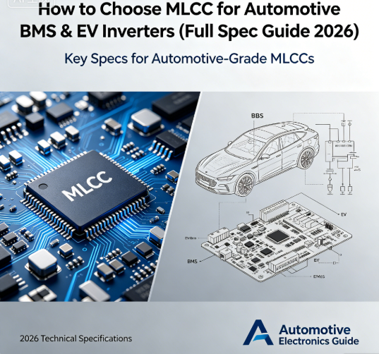
How to Choose MLCC for Automotive BMS & EV Inverters (Full Spec Guide 2026)
Keywords: automotive MLCC, BMS MLCC, EV inverter MLCC, AEC-Q200 MLCC
Overview
In 2026, electric vehicle demand continues to boom, and MLCCs have become one of the most critical components in BMS (Battery Management Systems), OBC, and motor inverters. Choosing the wrong MLCC can lead to overheating, vibration failure, or even safety risks.
As a professional MLCC manufacturer, we summarize the real engineering requirements for automotive electronics and provide a complete selection guide you can apply directly.
Key MLCC Requirements for Automotive EV Systems
- AEC-Q200 Certification: Mandatory for all automotive onboard electronics. Non-certified MLCCs risk failure under temperature cycling and vibration.
- Wide Temperature Range: -40℃ to 125℃ is standard; high-temperature applications require -55℃ to 150℃.
- High Vibration Resistance: Vehicles experience long-term vibration, so packaging strength and solderability are essential.
- Low ESR & Stable Capacitance: Especially important for power filtering in inverters and BMS.
Recommended MLCC Series for EV Applications
- Automotive Grade Series (AEC-Q200): Suitable for BMS, MCU, and sensor circuits. Stable capacitance, excellent temperature performance.
- High-Voltage Series: For EV inverters and on-board chargers. Withstand voltage up to 100V–1000V, strong anti-breakdown performance.
- Low ESR Series: Reduces heat generation and improves power efficiency in high-current environments.
Why Choose Our MLCCs for EV Projects
- Full AEC-Q200 & IATF16949 certified
- Stable supply, 7–15 day lead time
- Cost 20%–35% lower than Japanese brands
- Free samples and technical support available
Get Your Free Selection Sheet: Contact us to receive the Automotive MLCC Selection Checklist including recommended part numbers, voltage ratings, and packaging sizes for BMS and inverters.
Blog 2: High-Frequency MLCC for 5G & Radar: Low ESR Design & Application Tips
Keywords: high frequency MLCC, low ESR MLCC, 5G MLCC, radar MLCC
Introduction
High-frequency equipment such as 5G base stations, automotive radar, and communication modules places strict demands on MLCC performance. Traditional MLCCs suffer from high loss, signal interference, and unstable capacitance at high frequencies.
In this article, we explain how to select high-frequency MLCCs and optimize your circuit performance.
Core Performance Indicators for High-Frequency MLCC
- Low ESR (Equivalent Series Resistance): Lower ESR means less heat and better filtering at GHz frequencies.
- Stable Capacitance at High Frequency: Avoid significant capacitance drop in 1GHz–6GHz bands.
- Low Loss Factor (tanδ): Reduces signal attenuation and improves transmission efficiency.
- Miniature Package Size: 0201, 01005 packages for compact RF modules.
Our High-Frequency MLCC Advantages
- Optimized electrode and dielectric formula for 1GHz–6GHz applications
- ESR as low as 3–8 mΩ
- Excellent high-frequency stability
- Available in 01005 to 0603 sizes
- Mass production capacity ensures stable supply
Application Scenarios
5G communication modules, Automotive 77GHz radar, RF transceivers, WiFi 6/7 devices, UAV communication systems
Support & Samples: We provide free high-frequency MLCC samples for testing. Our engineering team can also help with model matching and PCB layout suggestions.
X7R vs X8R vs Y5V MLCC: Which Dielectric Is Right for Your Project?
X7R MLCC, X8R MLCC, Y5V MLCC, MLCC dielectric comparison
Executive Summary
The dielectric material determines the temperature stability, capacitance tolerance, and application scope of MLCCs. Many engineers choose the wrong type, leading to product failure or unnecessary cost increases.
This guide compares X7R, X8R, and Y5V clearly so you can make the best choice.
MLCC Dielectric Comparison Table
| Type | Temperature Range | Capacitance Change | Typical Applications |
|---|---|---|---|
| X7R | -55℃ to 125℃ | ±15% | Consumer electronics, industrial power, automotive |
| X8R | -55℃ to 150℃ | ±15% | High-temp automotive, AI servers, industrial |
| Y5V | -30℃ to 85℃ | +22% / -82% | Low-cost general circuits |
Selection Recommendations
- Use X8R for high-temperature environments (AI servers, automotive engine compartments, LED drivers).
- Use X7R for general industrial & automotive (Most BMS, power supplies, controllers).
- Use Y5V only for low-cost, low-stability consumer products (Toys, small appliances, non-critical circuits).
Our MLCC Dielectric Series
- X7R: full sizes, high reliability
- X8R: automotive & high-temperature grade
- Custom dielectric formulas available for OEM projects
Quick Tip: Never use Y5V in automotive or server power circuits. It will cause severe capacitance drift at extreme temperatures.
Contact Us for Custom Solutions: Tell us your working temperature and voltage, and we will recommend the best dielectric and MLCC model within 12 hours.
MLCC Soldering & PCB Design Mistakes That Cause Early Failure
MLCC soldering, MLCC PCB design, MLCC failure, MLCC cracking
Introduction
Up to 40% of MLCC failures are not caused by component quality, but by poor soldering processes or unreasonable PCB layout.
As an MLCC manufacturer with 12 years of experience, we summarize the most common mistakes and how to fix them.
Common MLCC Failure Causes from Design & Production
- Excessive Thermal Stress During Soldering: Reflow temperature too high or uneven heating leads to MLCC cracking.
- PCB Pad Design Too Large: Causes excessive stress during temperature cycling.
- Insufficient Clearance Between Components: Increases thermal interference and vibration risk.
- Incorrect Solder Amount: Too much solder causes internal stress; too little leads to cold joints.
Our Design & Assembly Suggestions
- Recommended reflow temperature: 235℃–250℃
- Optimize pad length to match MLCC package size
- Increase creepage distance for high-voltage MLCCs
- Use anti-vibration layout for automotive and industrial products
How Our MLCCs Improve Reliability
- Strengthened ceramic body to resist cracking
- Stable electrode structure for better solderability
- Available with flexible termination options for anti-vibration
- Full reliability test before shipment
Free Resource: Download our MLCC PCB Design & Soldering Guide to reduce failure rates by over 60%.
5: Custom MLCC Solutions for Industrial Control & High-Voltage Equipment
custom MLCC, high voltage MLCC, industrial MLCC, heavy-duty MLCC
Overview
Standard MLCCs often cannot meet the requirements of industrial control, power inverters, high-voltage power supplies, and automation equipment.
We provide fully customized MLCC solutions to meet special voltage, size, temperature, and reliability demands.
Custom MLCC Services We Provide
- Custom voltage ratings: 10V – 3000V
- Custom package sizes: 01005 to 2225
- Custom dielectric: X7R, X8R, high stability
- Custom termination: nickel barrier, silver-palladium, flexible termination
- Custom certification: RoHS, Reach, AEC-Q200, IATF16949
Typical Industrial Applications
Industrial PLC & controllers, PV inverters & energy storage systems, High-voltage power supplies, Motor drivers & frequency converters, Automation equipment
Benefits of Partnering With Us
- Strong R&D team for fast custom development
- Stable mass production capacity
- Competitive pricing for bulk orders
- Free technical evaluation and sample production
- Short lead time for customized products
Next Step: Send us your parameters: voltage, capacitance, size, temperature range, and application. We will provide a free custom MLCC proposal and quotation within 24 hours.
Contact Us
Email: hyc2355937758@gmail.com
WhatsApp: +86-15913754866 / +86-18824523083
Website: www.barronmlcc.com
High-Capacity MLCC for AI Servers Data Centers 2026 Selection Supply Guide
2026 MLCC Price Surge Samsung Murata Price Adjustment Impact
Related Article




