
Military-Grade MLCC for Aerospace MIL-PRF-123/GJB 192A Standards Radiation Hardening Extreme Environment Reliability Zero-Defect Design
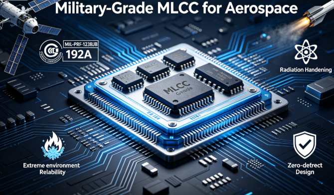
Military-Grade MLCC for Aerospace MIL-PRF-123/GJB 192A Standards Radiation Hardening Extreme Environment Reliability Zero-Defect Design
Company: Dongguan Musen LaidunElectronic Technology Co., Ltd.
Military-Grade MLCC, Aerospace Capacitor, MIL-PRF-123, GJB 192A, Radiation-Hardened MLCC, High Vibration & Shock Resistance, Vacuum Outgassing, Zero-Defect Reliability
mu sen Introduction
Aerospace and defense represent the most demanding application fields for electronic components, with zero tolerance for failure. From launch vehicles, satellites, and space stations to fighter jets, missiles, radars, and military communication systems, the failure of any single component can lead to mission failure, equipment destruction, or even casualties. As the most widely used passive component, MLCC is extensively deployed in core systems such as power management, signal processing, radar RF, and guidance control. Its performance and reliability directly determine the success of national defense equipment and space missions.
Aerospace and defense environments are the harshest on Earth: extreme temperature cycles from -65℃ to 200℃, tens of thousands of g shock acceleration during rocket launch, high-energy particle radiation in space, material outgassing under high vacuum, continuous random vibration, salt spray corrosion, and electromagnetic pulse interference. Ordinary consumer, industrial, or even automotive-grade MLCCs fail rapidly in these conditions, requiring specially designed military-grade high-reliability MLCCs.
1. Military MLCC Certification System & Grade Classification
1.1 Global Mainstream Military Standard Certifications
Military-grade MLCC must pass strict military standard certifications to enter defense and aerospace supply chains. The following are the world's most authoritative military standards:
| Standard Code | Issuing Authority | Application Scope | Core Requirements |
|---|---|---|---|
| MIL-PRF-123 | U.S. Department of Defense | General specification for military fixed capacitors | Foundation standard for global military MLCC, defining performance, testing, and quality assurance |
| GJB 192A | China Commission of Science, Technology and Industry for National Defense | General specification for military multilayer ceramic capacitors with reliability indicators | Mandatory standard for Chinese military MLCC, equivalent to MIL-PRF-123 |
| MIL-PRF-55681 | U.S. Department of Defense | High-reliability multilayer ceramic fixed capacitors | Space-grade high-reliability standard, stricter than MIL-PRF-123 |
| ESCC 3009 | European Space Agency (ESA) | European space multilayer ceramic capacitors | European space-specific standard, focusing on radiation resistance and vacuum performance |
| QML/QPL | U.S. Defense Logistics Agency | Qualified Manufacturer List / Qualified Product List | Only QML/QPL listed manufacturers and products can be used in U.S. military equipment |
1.2 Military MLCC Reliability Grade Classification
Based on reliability requirements and application scenarios, military MLCC is divided into four grades, with higher grades requiring stricter reliability:
- Grade M (Military): Basic military grade, suitable for general military ground equipment and non-critical airborne equipment
- Grade S (High-Reliability Military): Stricter testing requirements, suitable for critical airborne and shipborne equipment
- Grade P (Space): Highest reliability grade, suitable for satellites, space stations, launch vehicles and other space equipment
- Grade R (Radiation-Hardened Space): Specially radiation-hardened design, suitable for deep space exploration and high-radiation orbit satellites
1.3 Essential Differences Between Military & Industrial Grade MLCC
The differences between military and industrial MLCC are comprehensive, with strict controls at every stage from raw materials to final delivery:
| Comparison Item | Industrial Grade MLCC | Military Grade P MLCC |
|---|---|---|
| Raw Materials | Industrial grade, average batch stability | Ultra-high purity aerospace grade, 100% batch inspection, traceable to mine |
| Production Environment | Ordinary clean workshop | Class 100+ ultra-clean workshop, fully dust-free and pollution-free |
| Factory Screening | Sampling inspection | 100% full inspection + 100% aging screening + 100% X-ray inspection |
| Reliability Testing | 1000-hour high-temperature aging | 3000-hour HTOL + 1000 thermal cycles + random vibration + shock testing |
| Traceability | Batch traceability | Unique serial number per unit, full lifecycle traceability |
| Failure Rate | ≤100 FIT | ≤0.1 FIT (≤0.1 failures per billion hours) |
2. Seven Core Special Requirements for Aerospace & Defense MLCC
2.1 Extreme Temperature Tolerance
Aerospace equipment operates in the most extreme temperature environments: up to 120℃ on the sunlit side of space, as low as -180℃ on the shaded side; up to 200℃ in fighter jet engine compartments; as low as -65℃ for military equipment in the Arctic. Military MLCC must operate stably over -65℃~200℃, with some space-grade products extending to -55℃~250℃.
2.2 High Vibration & Shock Resistance
Launch vehicle shock acceleration can exceed 20,000g, fighter jet maneuver acceleration reaches 15g, and missile flight vibration frequency can reach 2000Hz. Military MLCC must withstand these extreme mechanical stresses without ceramic cracking, terminal detachment, or performance drift.
2.3 Radiation Hardening Capability
Space contains large amounts of high-energy particles including protons, electrons, and heavy ions, causing radiation damage to electronic components. MLCC radiation damage manifests as:
- Total Ionizing Dose (TID): Long-term accumulated radiation causes dielectric aging, increased leakage, and capacitance decay
- Single Event Effect (SEE): Ionization from a single high-energy particle passing through the dielectric may cause instantaneous leakage or permanent breakdown
Space-grade MLCC must be specially radiation-hardened, withstanding TID ≥100krad(Si), and some deep space products exceeding 1Mrad(Si).
2.4 Vacuum Environment Adaptability
Space is a high-vacuum environment. Organic materials (adhesives, coatings) in ordinary MLCC volatilize in vacuum, causing outgassing. Outgassed contaminants deposit on precision components such as optical lenses and sensors, leading to equipment failure. Military MLCC must adopt all-inorganic structures with no organic materials, meeting NASA ASTM E595 low-outgassing standards.
2.5 Ultra-Low Leakage Current Requirement
Spacecraft typically rely on solar cells and batteries, with extremely limited energy resources. MLCC leakage current must be controlled at extremely low levels to reduce energy consumption. Ultra-low leakage is also essential for the normal operation of high-precision sensors and signal processing circuits. Military MLCC has insulation resistance ≥10^13Ω, far higher than industrial grade 10^10Ω.
2.6 Ultra-Long Life Requirement
Geosynchronous orbit satellites have a design life of over 15 years, and deep space probes can operate for decades. MLCC must maintain stable performance throughout the entire lifecycle without any failure, requiring extremely high long-term reliability and aging resistance.
2.7 Zero-Defect & Traceability Requirement
Aerospace and defense missions allow no defects, requiring zero-defect delivery of military MLCC. Each MLCC must have a unique identifier, enabling traceability to raw material sources, production time, equipment, and inspection data for rapid troubleshooting and analysis.
3. Special MLCC Failure Mechanisms Under Extreme Environments
3.1 Thermal Cycle Fatigue Cracking
Extreme temperature cycles generate huge thermal stress inside MLCC. Repeated thermal expansion and contraction cause micro-cracks in the ceramic body. As cycles increase, micro-cracks propagate, eventually leading to ceramic cracking, delamination, or open circuit. This is one of the most common failure modes in space equipment.
3.2 Radiation-Induced Dielectric Aging
High-energy particle radiation destroys the crystal structure of ceramic dielectrics, creating lattice defects and trap centers. This reduces insulation resistance, increases leakage current, and causes capacitance decay. Severe radiation damage leads to dielectric breakdown and permanent short circuit.
3.3 Vacuum Outgassing Contamination
Organic adhesives and epoxy coatings in ordinary MLCC volatilize in high vacuum, producing condensable volatiles. These deposit on surrounding optical components, solar panels, and sensors, degrading performance or causing complete failure.
3.4 Mechanical Shock Fracture
Instantaneous high shock from rocket launch, missile flight, or artillery explosion generates huge inertial forces inside MLCC, causing ceramic fracture, terminal detachment, or solder joint failure. Large-package MLCCs are more susceptible to shock damage due to their greater mass.
3.5 Electromigration Failure
Under the combined action of high temperature and high electric field, metal ions in MLCC internal electrodes undergo electromigration, leading to electrode thinning, open circuit, or short circuit. This failure mode is particularly common in long-term powered space equipment.
4. Military MLCC Selection Standards
4.1 Dielectric Selection: Stability First
| Dielectric Type | Temperature Characteristic | Radiation Resistance | Aging Characteristic | Application Scenarios |
|---|---|---|---|---|
| C0G/NPO | ±30ppm/℃ | Excellent | No aging | Signal processing, clock, RF, high-precision sampling circuits |
| X7R | ±15% (-55~125℃) | Good | Low aging | Power filtering, decoupling, energy storage circuits |
| X8R | ±15% (-55~150℃) | Good | Low aging | High-temperature environment power circuits |
| X5R | ±15% (-55~85℃) | Fair | Medium aging | Prohibited in any aerospace and defense equipment |
Selection Iron Rule: X5R dielectric is prohibited in all aerospace and defense equipment; C0G dielectric is mandatory for critical circuits; X7R or X8R dielectric is preferred for power circuits.
4.2 Voltage Derating Standards: Strictest Requirements
To ensure reliability under extreme environments, military MLCC requires much stricter voltage derating than industrial equipment:
| Application Grade | DC Voltage Derating Multiple | AC Voltage Derating Multiple |
|---|---|---|
| Grade M (Military Ground) | ≥2.5x | ≥3.5x |
| Grade S (Airborne/Shipborne) | ≥3.0x | ≥4.0x |
| Grade P (Space) | ≥3.5x | ≥4.5x |
| Grade R (Deep Space) | ≥4.0x | ≥5.0x |
4.3 Temperature Derating Standards
- C0G dielectric: Max operating temp 150℃, recommended operating temp ≤125℃
- X7R dielectric: Max operating temp 125℃, recommended operating temp ≤100℃
- X8R dielectric: Max operating temp 150℃, recommended operating temp ≤125℃
- Space equipment: MLCC operating temp ≤70% of maximum rated temperature
4.4 Package Selection
- Prefer small packages: 0402/0603 packages have lower mass and better shock/vibration resistance
- High vibration/shock scenarios: Mandatory flexible termination MLCC, improving bending resistance by 5x+
- Space equipment: Prohibit 1206 and larger packages unless specially structurally reinforced
- All military MLCC must adopt Precious Metal Electrode (PME) or high-reliability Base Metal Electrode (BME) structures
4.5 Certification & Special Requirements
- Must pass corresponding grade military standard certification (MIL-PRF-123/GJB 192A)
- MLCC for vacuum environments must meet NASA ASTM E595 low-outgassing standards
- MLCC for radiation environments must provide radiation test reports
5. Aerospace & Defense PCB Design & Process Specifications
5.1 Layout Specifications
- MLCC should be kept away from heat sources such as power tubes, engines, and heat sinks
- Absolutely prohibit placing MLCC in PCB stress concentration areas such as board edges, screw holes, and depaneling lines
- MLCC in high-vibration areas should adopt symmetrical layout to avoid unilateral stress
- MLCC in critical circuits should be as close as possible to IC pins to shorten current loop length
- Strictly isolate high-voltage circuits from low-voltage circuits to avoid electromagnetic interference and high-voltage breakdown
5.2 Routing Specifications
- Power and ground traces should be short and wide, width ≥2mm, thickness ≥2oz, to reduce trace resistance and inductance
- Use 2~4 vias per MLCC for power and ground connections, via diameter ≥0.4mm, to reduce via inductance and resistance
- Avoid right-angle and acute-angle traces, use 45-degree or arc transitions to reduce stress concentration
- Signal circuits should form complete current loops to avoid long return paths
- Sensitive signal traces should be kept away from power and high-frequency traces to avoid crosstalk
5.3 Soldering Process Specifications
- Adopt military-grade lead-free solder, compliant with RoHS and military environmental requirements
- Reflow ramp rate ≤2℃/s, peak temperature ≤235℃ to avoid thermal stress damage
- Prohibit manual soldering of MLCC in critical circuits to ensure soldering quality consistency
- Perform 100% X-ray inspection after soldering to check for cold joints, shorts, voids, and other defects
- Perform 100% optical inspection to check for ceramic cracking, terminal damage, and other appearance defects
5.4 Reinforcement & Protection Processes
- MLCC in high-vibration/shock areas should be epoxy-dot reinforced using military-grade epoxy resin
- Apply military-grade conformal coating to the entire PCB for moisture, salt spray, and mold protection
- Space equipment PCBs should be potted using low-outgassing potting materials
- All connectors and interfaces should use military-grade aviation plugs to ensure reliable connection
6. Typical Scenario Application Solutions
6.1 Space Satellite Systems
Core Requirements: >15 years life, radiation resistance, low outgassing, high reliability
Selection Solution:
- Power management: 0603 10μF 50V Military X7R Grade P
- Signal processing: 0402 100nF 25V Military C0G Grade P
- RF circuit: 0402 1nF 50V High-Frequency Military C0G Grade R
Design Points: Adopt voltage derating above 3.5x; use low-outgassing materials; implement radiation hardening design; pass 3000-hour high-temperature aging test.
6.2 Airborne Systems
Core Requirements: Wide temperature range, high vibration, high reliability, long life
Selection Solution:
- Engine compartment: 0603 1μF 100V Military X8R Grade S Flexible Termination
- Avionics system: 0402 0.1μF 50V Military C0G Grade S
- Power filtering: 0805 22μF 25V Military X7R Grade S
Design Points: Adopt voltage derating above 3x; use flexible termination for all large-package MLCC; pass 1000 thermal cycles and random vibration tests.
6.3 Guided Weapon Systems
Core Requirements: High shock, fast response, high reliability, single-use
Selection Solution:
- Guidance circuit: 0402 10nF 50V Military C0G Grade M
- Power decoupling: 0603 1μF 25V Military X7R Grade M
- Fuse circuit: 0402 100pF 100V Military C0G Grade M
Design Points: Adopt voltage derating above 2.5x; epoxy-dot reinforce all MLCC; pass 20,000g shock test.


6.4 Military Radar Systems
Core Requirements: High frequency, low loss, high stability, anti-interference
Selection Solution:
- RF front-end: 0402 1pF~100nF High-Frequency Military C0G Grade S
- Power filtering: 0805 10μF 50V Military X7R Grade S
- Clock circuit: 0402 10pF 50V Military C0G Grade S
Design Points: Use C0G dielectric for all critical circuits; optimize power integrity design to reduce noise; perform EMC testing to ensure anti-interference ability.
7. Common Misconceptions & Pitfalls
- Misconception 1: Industrial grade MLCC can replace military grade MLCC → Truth: Industrial grade MLCC has no military certification, cannot withstand extreme environments, and will cause mission failure.
- Misconception 2: Sufficient voltage rating means suitability for high-voltage environments → Truth: Military MLCC requires voltage, temperature, and radiation derating, not just rated voltage.
- Misconception 3: Radiation only affects semiconductor devices, not MLCC → Truth: High-energy particle radiation destroys ceramic dielectric structure, causing increased leakage and breakdown.
- Misconception 4: Vacuum only affects seals, not electronic components → Truth: Organic materials in ordinary MLCC outgas in vacuum, contaminating optical devices.
- Misconception 5: Large-package capacitors have higher capacity and better filtering → Truth: Large-package capacitors have higher mass and poorer shock/vibration resistance, prone to failure in high-vibration environments.
8. Military MLCC Design Checklist
- Select corresponding grade military MLCC according to application scenario
- Prefer C0G dielectric for critical circuits, X7R/X8R for power circuits
- Implement strict voltage and temperature derating standards
- Prefer small packages and flexible termination MLCC
- Verify MLCC radiation resistance and low-outgassing performance
- Ensure MLCC has complete traceability
- Optimize PCB layout and routing to avoid stress concentration and EMI
- Adopt military-grade soldering process, control reflow temperature profile
- Epoxy-dot reinforce MLCC in high-vibration areas
- Perform comprehensive reliability tests including aging, thermal cycling, vibration, and shock
- Retain all certification and test reports for military audit
mu sen Conclusion
When designing aerospace and defense equipment, engineers must abandon consumer and industrial design thinking, strictly follow military standards and specifications, and implement comprehensive quality control from selection, layout, soldering to testing. Only by adhering to the zero-defect design philosophy can we create high-performance national defense equipment and space systems that withstand extreme environmental tests.
Dongguan Musen Leyton Electronic Technology Co., Ltd. provides a full range of military-grade MLCC products compliant with MIL-PRF-123, GJB 192A and other military standards, covering C0G/X7R/X8R dielectrics, 0402~1206 packages, 6.3V~3000V voltage range, including radiation-hardened, low-outgassing, and flexible termination high-reliability series. We meet the needs of various extreme scenarios such as aerospace, military weapons, and radar communications.
MLCC High-Reliability Application in PV Energy Storage Systems 25-Year Long-Life Design 1500V High
High-Reliability MLCC Application in Medical Electronics Medical Grade Certification System Biocompatibility Sterilization Resistance Ultra-Low Leakage Full-Scenario Selection Solutions
Related Article




