
MLCC Dielectric Selection Special Manual C0G / X5R / X7R / X8R Full Comparison Application Guide
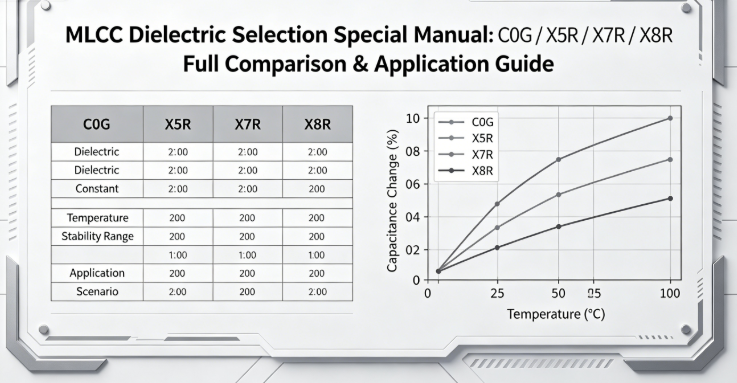
MLCC Dielectric Selection Special Manual: C0G / X5R / X7R / X8R Full Comparison & Application Guide
mu sen Introduction
MLCC dielectric material is the core factor determining capacitance stability, temperature resistance, DC-bias performance, and high-frequency behavior. Many engineers only select by capacitance and voltage rating, ignoring dielectric differences, leading to failures such as capacitance drift, high-temperature breakdown, and excessive high-frequency loss.
Four mainstream MLCC dielectrics: C0G (NP0), X5R, X7R, X8R. They differ greatly in stability, bias, frequency, and temperature. The correct logic is: match dielectric characteristics to application requirements.
This manual deeply explains the four dielectrics, provides comparison tables, application guidelines, failure cases, and a complete selection system to help you avoid dielectric selection failures.
1. Core Characteristics of 4 Mainstream MLCC Dielectrics
1.1 C0G (NP0) – High Precision & High Stability, Best for High Frequency
- Class I dielectric, no ferroelectric effect, extremely stable
- Temperature coefficient: ±30ppm/℃ (-55℃~125℃)
- Tolerance: ±0.1% ~ ±1%
- No DC-bias attenuation, no aging
- Ultra-low ESR, high SRF, ideal for >10MHz
- Disadvantage: max capacitance ≤1μF, high cost
1.2 X5R – Economic Type, General Consumer Applications
- Class II dielectric, medium stability
- Capacitance change: ±15% (-55℃~85℃)
- Tolerance: ±10% ~ ±20%
- Obvious decay under ≥200V
- Only for ≤1MHz low frequency
- Disadvantage: poor heat resistance, fast aging
1.3 X7R – Cost-Effective, Medium High-Temperature General Use
- Better than X5R in stability & bias
- Capacitance change: ±15% (-55℃~125℃)
- Tolerance: ±5% ~ ±10%
- Medium decay under ≥500V
- For 1MHz~5MHz medium frequency
1.4 X8R – High Performance, Best for High Temp / High Voltage / High Frequency
- Upgraded version of X7R
- Capacitance change: ±15% (-55℃~150℃)
- Very low decay under ≤1500V
- Slow aging, strong anti-polarization fatigue
- Excellent for 5MHz~10MHz
- Cost higher than X5R/X7R


2. Core Parameter Comparison Table
| Dielectric | Temp Range | Temp Coefficient | Cap Tolerance | HV Bias | HF Performance | Max Cap | Cost |
|---|---|---|---|---|---|---|---|
| C0G (NP0) | -55~125℃ | ±30ppm/℃ | ±0.1%~±1% | No decay | Excellent (10MHz+) | ≤1μF | High |
| X5R | -55~85℃ | ±15% | ±10%~±20% | Strong decay | Normal (≤1MHz) | ≤100μF | Low |
| X7R | -55~125℃ | ±15% | ±5%~±10% | Medium decay | Medium (1~5MHz) | ≤47μF | Medium |
| X8R | -55~150℃ | ±15% | ±5%~±10% | Very low decay | Excellent (5~10MHz) | ≤10μF | Medium-High |
3. Full-Scenario MLCC Dielectric Selection Guide
3.1 Consumer Electronics (Router, Earphone, Power Bank)
- Recommended: X7R (core), X5R (non-core), C0G (RF)
- Taboo: Do not use X8R (waste cost), C0G for large-cap filtering
3.2 Industrial General (Inverter, Industrial Power)
- Recommended: X7R (general), X8R (≥400V), C0G (high-frequency control)
- Taboo: No X5R (overheating failure)
3.3 Industrial High-Temp & High-Voltage (PV, PCS, HV Power)
- Recommended: X8R first, C0G for high-frequency
- Taboo: No X5R/X7R (drift & fast aging)
3.4 Automotive (OBC, BMS, Power Domain)
- Recommended: AEC-Q200 X8R (power), X7R (cockpit), C0G (radar)
- Taboo: No X5R, no non-automotive grade
3.5 High-Frequency (SiC/GaN, Fast Charger)
- Recommended: X8R (5~10MHz), C0G (>10MHz), X7R (1~5MHz)
- Taboo: No X5R, no X7R for ≥5MHz core circuits
4. Real Dielectric Selection Failure Cases
Case 1: X5R used in 105℃ industrial power → rapid aging
Failure: 25% capacitance drop after 6 months
Cause: X5R max temp only 85℃
Fix: Replace with X7R / X8R
Case 2: X7R used in 6MHz GaN charger → high loss & heat
Fix: Replace with X8R, ESR <3mΩ
Case 3: X7R used in 800V automotive OBC → bias aging
Fix: Replace with automotive X8R
Case 4: X7R used in 15MHz RF → signal drift
Fix: Replace with C0G
5. Common Dielectric Selection Misconceptions
Fact: Temperature limits differ: 85℃ / 125℃ / 150℃
Fact: Low max capacitance, high cost
Fact: Severe bias decay and high loss
Fact: Higher failure risk increases total cost
Fact: HV needs X8R/C0G
6. MLCC Dielectric Selection Checklist
- Temperature range ≥ application max working temp
- HV (≥400V): choose X8R or C0G
- HF (≥5MHz): choose X8R or C0G
- High precision & RF: use C0G
- Balance cost and performance
- Automotive: use AEC-Q200 qualified X8R
- Large capacitance: use X5R/X7R
- Never substitute low-grade dielectrics
mu sen Conclusion
The core of MLCC dielectric selection is matching characteristics to the application. No dielectric is universally “best” — only suitable or not.
C0G for high-frequency & high-precision; X5R for low-cost consumer; X7R for general industrial; X8R for high-temperature, high-voltage, high-frequency, and automotive.
Most MLCC failures are caused by wrong dielectric selection, not poor quality. Following this guide ensures stable, reliable, and cost-effective design.
Dongguan Musen Leyton Electronic Technology Co., Ltd. provides full-series C0G, X5R, X7R, X8R MLCCs. Our high-performance X8R, automotive-grade X8R, and high-precision C0G support extreme environments. We offer free samples, testing, and professional selection guidance.
Contact Us
MLCC Package Selection PCB Pad Design Manual Pad Specification Soldering Process Layout Avoidance
MLCC Testing Reliability Verification Practical Manual Full Parameter Testing Qualification Standards
Related Article




