Navigating Ultrasonic Cleaning Risks Preventing Acoustic Cavitation Damage in MLCC Assemblies
Navigating Ultrasonic Cleaning Risks: Preventing Acoustic Cavitation Damage in MLCC Assemblies
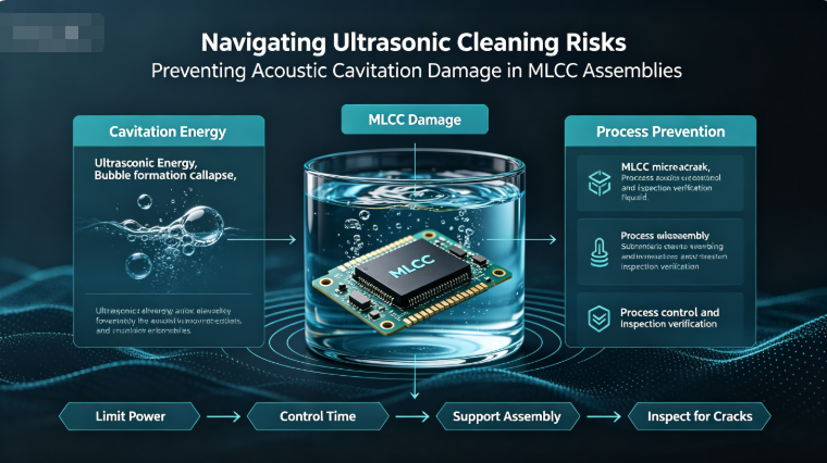
Following surface-mount reflow and flux residue removal, many electronics manufacturing lines utilize ultrasonic cleaning tanks to scrub printed circuit boards (PCBs) clean of ionic contaminants. While highly effective for cleaning complex geometries, ultrasonic cleaning can introduce a hidden hazard for brittle components: acoustic cavitation damage and mechanical resonance cracking in Multilayer Ceramic Capacitors (MLCCs).
For manufacturing engineers and assembly quality teams sourcing components via www.barronmlcc.com, understanding the mechanics of ultrasonic damage is critical to preventing latent component failures before boards leave the factory floor.
The Physics of Ultrasonic Cavitation and Resonance
Ultrasonic cleaners operate by generating high-frequency sound waves (typically between 20 kHz and 120 kHz) in a liquid cleaning bath, producing microscopic vapor bubbles that collapse violently near solid surfaces.
- Cavitation Erosion: The microscopic shockwaves generated by collapsing bubbles can pit metal terminations, erode solder joints, and micro-fracture outer ceramic layers if parts are exposed to excessive power densities or prolonged cleaning cycles.
- Resonant Frequency Coupling: If the ultrasonic bath frequency matches or harmonizes with the natural mechanical resonant frequency of small ceramic capacitors or the local PCB span, the board acts as an acoustic diaphragm. This subjects surface-mounted MLCCs to severe vibrational fatigue, initiating internal micro-cracks that mirror mechanical board-flex failures.
High-Risk Factors During PCB Cleaning
Certain manufacturing variables drastically increase the likelihood of ultrasonic-induced damage:
- High-Frequency Sweep Discrepancies: Operating cleaning tanks without frequency modulation or sweeping can create localized standing waves with extreme acoustic intensity peaks.
- Improper Board Fixturing: Rigidly clamping PCBs directly against the vibrating bottom or side walls of the ultrasonic tank transmits mechanical energy with zero acoustic damping.
- Vulnerable Component Selection: Miniature case sizes (such as 0402 and 0201) and brittle Class 2 dielectrics mounted near high-amplitude vibration nodes are at the highest risk.
Best Practices for Safe Aqueous Cleaning
Manufacturing facilities can eliminate ultrasonic risk without sacrificing cleanliness by enforcing strict process controls:
- Optimize Bath Parameters: Select optimized frequencies (higher frequencies like 80 kHz to 120 kHz produce smaller, gentler cavitation bubbles compared to harsh 20 kHz systems) and limit immersion durations.
- Use Acoustic Damping Fixtures: Ensure PCBs are suspended in specialized soft-contact baskets or non-rigid racks rather than resting directly on the vibrating tank floor.
- Alternative Cleaning Chemistries: Where ultrasonic risks cannot be fully mitigated, transition to inline spray-under-stencil or chemical wash systems that rely on fluid velocity rather than acoustic cavitation.
Safeguarding Assembly Integrity with HLAIPOPNY
Achieving robust, zero-defect electronics manufacturing requires safeguarding component integrity across every stage of production—from component sourcing to final cleaning and test.
To explore our inventory of high-reliability surface-mount capacitors engineered to withstand rigorous industrial processing, visit us at www.barronmlcc.com.
HLAIPOPNY — Delivering manufacturing excellence and uncompromising component durability for the global electronics industry.
What specific aqueous cleaning methods or bath frequencies do your manufacturing lines utilize for post-reflow flux removal?
Get In Touch & Request Free Samples
Email: hyc2355937758@gmail.com
WhatsApp: 8615913754866
Tel: 86+18824523083
Website: www.barronmlcc.com
Demystifying MLCC Capacitance Measurement Why Multimeter Readings Differ From Datasheet Specifications
Engineering Resilience How SoftTermination MLCCs Protect PCBs Against Mechanical Flex Cracking
Related Article