
Related Article

For hardware design engineers and procurement specialists sourcing passive components, a common phenomenon often causes unexpected circuit instability: a Multi-Layer Ceramic Capacitor (MLCC) rated for 10µF suddenly acts like a 3µF or 4µF capacitor once installed and powered on. This drop is not a defect; it is the DC bias effect inherent to Class II ceramic dielectrics (such as X7R and X5R).
Understanding MLCC DC Bias Characteristics Why Your Capacitance Drops in Power Supply Circuits

When quality inspection or assembly technicians test incoming Multilayer Ceramic Capacitors (MLCCs) using a standard handheld digital multimeter, they frequently encounter a frustrating discrepancy: the measured capacitance is significantly lower than the nominal value stated on the manufacturer's datasheet. This variance rarely indicates a defective component; rather, it highlights the strict dependence of ceramic capacitors on specific test conditions.
Demystifying MLCC Capacitance Measurement Why Multimeter Readings Differ From Datasheet Specifications

Following surface-mount reflow and flux residue removal, many electronics manufacturing lines utilize ultrasonic cleaning tanks to scrub printed circuit boards (PCBs) clean of ionic contaminants. While highly effective for cleaning complex geometries, ultrasonic cleaning can introduce a hidden hazard for brittle components: acoustic cavitation damage and mechanical resonance cracking in Multilayer Ceramic Capacitors (MLCCs).
Navigating Ultrasonic Cleaning Risks Preventing Acoustic Cavitation Damage in MLCC Assemblies
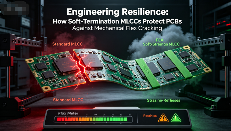
When printed circuit boards undergo rigorous mechanical assembly steps—such as depanelization, connector insertion, screw fastening, or in‑circuit testing (ICT)—standard surface‑mount components face intense physical strain. Because multilayer ceramic capacitors (MLCCs) are inherently brittle
Engineering Resilience How SoftTermination MLCCs Protect PCBs Against Mechanical Flex Cracking
