
Top 5 Most Common Questions About Automotive MLCC Peripheral Issues Solutions
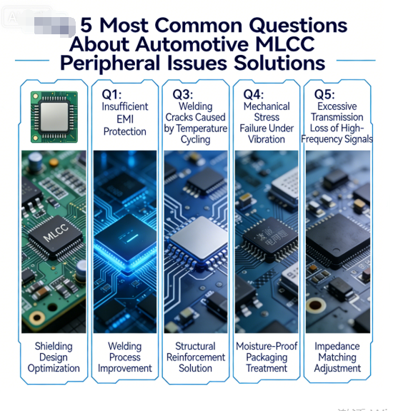
Top 5 Most Common Questions About Automotive MLCC Peripheral Issues & Solutions
Multi-layer ceramic capacitors (MLCCs) are the most widely used passive components in automotive electronics, supporting ADAS, infotainment, power supplies, LED lighting, and body control modules. While MLCCs themselves are reliable, peripheral application issues—such as capacitance drift, solder cracking, wrong dielectric selection, environmental stress, and grade mismatch—cause 70% of field failures.
These are the top 5 most frequently asked questions about automotive MLCC peripheral usage searched on Google by design engineers, quality teams, and component buyers. This article provides clear root causes, practical solutions, and reliable component suggestions to help you reduce failure rates and improve vehicle stability.
1. What Causes MLCC Capacitance Drift in High-Temperature Automotive Environments, and How to Prevent It?
Capacitance drift is one of the most common hidden failures in automotive electronics, especially in cabins, engine bays, and headlight units where temperatures fluctuate sharply. Even a small capacitance shift can lead to signal distortion, power instability, or sensor misalignment.
Root Causes
- Using low-stability dielectrics (such as Y5V) that change capacitance by ±20% or more under high heat.
- Exceeding the operating temperature range of commercial-grade MLCCs.
- Humidity absorption degrading the ceramic dielectric over time.
Prevention Solutions
- Use X7R or C0G/NP0 dielectrics for automotive applications:
- X7R: ±15% stability, –55°C to 125°C, ideal for power and filtering.
- C0G/NP0: ±0.005% stability, –55°C to 150°C, perfect for signal and sensor circuits.
- Select AEC-Q200 Grade 1 MLCCs rated to 150°C.
- Add conformal coating to protect against moisture.
Recommended Models
- Murata GRM32ER72A225KA88L (X7R, AEC-Q200)
- TDK CGA5E3X7R1H472K (C0G, high-temperature stability)
2. Why Do Automotive MLCCs Experience Solder Joint Cracking, and What Are the Best Fixes?
Solder joint cracking is the leading mechanical failure of automotive MLCCs, caused by thermal expansion mismatch and vibration. It often leads to intermittent power loss, system crashes, and no-fault-found (NFF) issues.
Root Causes
- Large temperature cycles (–20°C to 140°C) in vehicles create CTE mismatch between MLCC and PCB.
- Using rigid solder alloys with poor fatigue resistance.
- MLCC placed too close to PCB edges or mounting points.
- Improper reflow soldering profile.
Best Fixes
- Use SAC305 lead-free solder for better flexibility and thermal fatigue resistance.
- Design larger, rounded solder pads to distribute stress.
- Keep MLCCs at least 3mm away from board edges and fasteners.
- Optimize reflow profile: slow ramp ≤2°C/sec, peak temp ≤245°C.
- Apply underfill for high-vibration areas (engine bay, chassis).
Recommended Models
- Samsung CL32A105KB8NNNC (compact, low-stress package)
- KYOCERA AVX TCJ326K016R0500 (robust termination design)
3. How to Choose the Right Dielectric (X7R / X5R / C0G) for Automotive MLCC Applications?
Dielectric selection directly determines stability, temperature range, and service life. Many designers use the wrong dielectric, leading to performance degradation or early failure.
Comparison & Application Guide
| Dielectric | Temp Range | Capacitance Stability | Best For |
|---|---|---|---|
| C0G/NP0 | –55°C to 150°C | ±0.005% | Sensors, ADAS signals, precision circuits |
| X7R | –55°C to 125°C | ±15% | Power supplies, infotainment, LED drivers |
| X5R | –55°C to 85°C | ±15% | Low-temperature cabin modules only |
Selection Rules
- ADAS & sensors: Must use C0G.
- Engine bay & high-heat areas: Use X7R or C0G.
- Cabin & low-stress areas: X7R or X5R.
- Never use Y5V in any automotive application.
Recommended Models
- C0G: Murata GRM0335C1H100JW01D
- X7R: TDK CGA3E3X8R1H104K
4. What’s the Difference Between Automotive-Grade MLCC and Commercial MLCC, and Why AEC-Q200 Matters?
This is the most searched foundational question for buyers and junior engineers. Using commercial MLCCs in vehicles causes massive warranty risks.
Key Differences
| Item | Automotive Grade (AEC-Q200) | Commercial Grade |
|---|---|---|
| Temp Range | –55°C to 150°C | –20°C to 85°C |
| Vibration Resistance | 1000–3000Hz | 500Hz max |
| Reliability Testing | Full life cycle, thermal shock | Basic performance only |
| Humidity Resistance | IP67-level compatible | Unprotected |
Why AEC-Q200 Is Mandatory
AEC-Q200 is the global automotive electronic component reliability standard. It verifies:
- Temperature cycling performance
- Vibration and shock resistance
- Humidity and bias stability
- Solderability and lifetime
Non-AEC-Q200 MLCCs will fail early in harsh automotive environments.
Certified Brands
- Murata, TDK, Samsung, KYOCERA AVX
5. How to Avoid MLCC Failure Caused by Vibration, Humidity, and Voltage Surge in Vehicles?
Vibration, humidity, and voltage surges are the three biggest environmental threats to automotive MLCCs, leading to cracking, leakage, and breakdown.
Practical Protection Solutions
Vibration Resistance
- Select MLCCs with reinforced terminations.
- Keep components away from high-vibration areas (motors, fans, wheel arches).
- Use underfill adhesive around MLCCs.
Humidity Protection
- Use hermetic or epoxy-sealed MLCCs.
- Apply conformal coating on PCB.
- Store and assemble in low-humidity environments.
Voltage Surge Protection
- Choose MLCCs with voltage rating 1.5–2x the working voltage.
- Add TVS diodes in parallel for surge absorption.
- Avoid overvoltage during cold start or load switching.
Recommended Reliable Models
- Murata GRM0165R60J104KE01L (vibration-resistant)
- TDK CGA6E3X7R1H104K (high-voltage, surge-tolerant)
Final Thoughts
Most automotive MLCC failures are not caused by the component itself, but by peripheral application mistakes: wrong dielectric, poor solder design, environmental stress, or grade mismatch.
By solving these 5 common peripheral issues, you can greatly improve the reliability of automotive electronic systems, reduce failure rates, and lower after-sales costs.
If you need professional support for MLCC selection, PCB layout, or AEC-Q200 compliance, feel free to contact our team for customized solutions.
📩 Email: hyc2355937758@gmail.com
📱 +86 18824523083 | WhatsApp: +86 15913754866
📥 Free Download: Automotive MLCC Application & Reliability Checklist
Top 5 Most Common Electronic Component Peripheral Usage Problems
Top 5 Questions About MLCC Advantages 2026 Ceramic Capacitor Benefits
Related Article




