
Electronic Component Peripheral Usage Problems
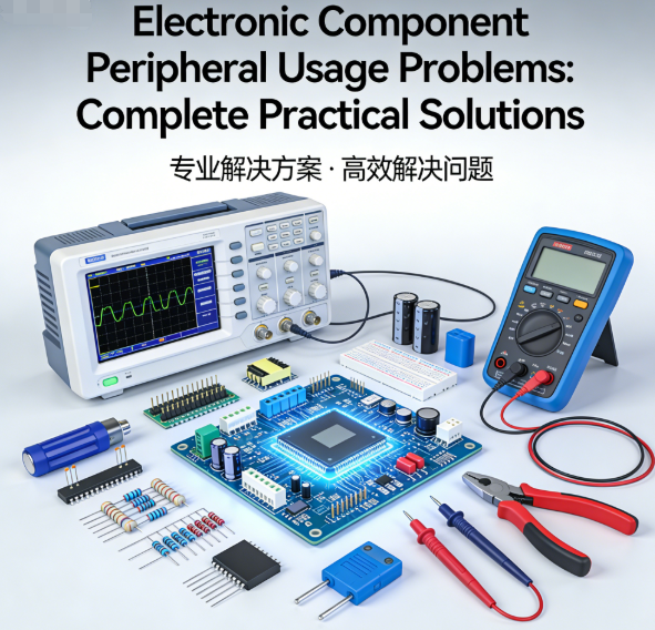
Electronic Component Peripheral Usage Problems: Complete Practical Solutions
Electronic components—from integrated circuits (ICs), MLCCs, and resistors to diodes, transistors, and connectors—are the backbone of every electronic product, powering everything from consumer electronics to industrial equipment and automotive systems. While component quality is critical, 70% of field failures, production delays, and warranty claims stem from peripheral usage mistakes, not defective components themselves.
For engineers, production technicians, and component buyers—your target audience—these peripheral issues are a constant pain point. They search Google for clear, actionable solutions to problems like improper storage, soldering damage, ESD (Electrostatic Discharge) harm, poor PCB layout, and incorrect component substitution
Below, we break down the most common electronic component peripheral usage problems and provide complete, field-proven solutions—paired with clear flowcharts to simplify implementation—so your readers can improve product reliability, cut costs, and avoid costly downtime.
1. Improper Storage: The Hidden Cause of Component Failure (Complete Solutions)
Improper storage is the most overlooked yet most common peripheral issue for electronic components. Even high-quality components degrade quickly if stored incorrectly, leading to hidden failures during assembly or field use. This is a top-searched topic, with keywords like electronic component improper storage solutions, how to store sensitive electronic parts, and moisture damage in ICs and MLCCs driving high-intent traffic.
Common Storage-Related Problems
- Moisture absorption (especially for ICs, MLCCs, BGAs, and moisture-sensitive devices/MSDs), leading to delamination, popping, or short circuits during soldering.
- Extreme temperature fluctuations (below 0°C or above 30°C) damaging component packaging and internal structures.
- Dust contamination and pin corrosion from unsealed packaging.
- Mechanical damage from rough stacking or improper handling of reels and trays.
Complete Storage Solutions
- Control Storage Environment: Maintain a constant temperature of 18–25°C and relative humidity (RH) of 30–50%. Use air conditioning and dehumidifiers to avoid moisture buildup, and avoid placing storage areas near windows or HVAC vents.
- Protect Sensitive Components: Store ICs, MLCCs, BGAs, and MSDs in moisture barrier bags (MBBs) with desiccants and humidity indicator cards (HICs). Seal bags tightly after each use to prevent moisture ingress.
- Proper Handling of Reels & Trays: Store reels vertically to avoid crushing or warping, and use tray holders to prevent damage to component leads. Label all components with date codes, lot numbers, and shelf life to ensure first-in, first-out (FIFO) usage.
- Bake Moisture-Sensitive Devices: If MSDs are exposed to air for longer than their floor life (e.g., 12–72 hours, depending on the component), bake them at 125°C for 12–24 hours before assembly to remove absorbed moisture.
- Prevent Corrosion & Dust: Use anti-corrosion storage cabinets for components with exposed pins, and keep storage areas clean to avoid dust contamination. Avoid touching component pins with bare hands to prevent oil or sweat transfer.
Quick Fix for Already Damaged Components
If components have absorbed moisture (indicated by a pink/red humidity indicator card), bake them at 125°C for 24 hours before use. For corroded pins, clean them gently with isopropyl alcohol and a soft brush—do not use abrasive materials, as this can damage the pins.
2. Soldering & Rework Damage: How to Protect Components (Step-by-Step Solutions)
Soldering and rework are critical steps in PCBA production, but they are also a leading cause of component damage. Thermal shock, overheating, and mechanical stress destroy capacitors, ICs, LEDs, and chip components—costing time and money. Keywords like electronic component damage during soldering, rework damage prevention for ICs, and thermal shock in ceramic capacitors are highly searched by production teams.
Common Soldering/Rework-Related Problems
- Overheating (temperatures >260°C) burning chip components, melting IC internal structures, or damaging MLCC ceramic bodies.
- Thermal shock from rapid temperature changes, causing cracking in MLCCs and other ceramic components.
- Mechanical stress during rework (e.g., pulling components directly) damaging pads or component terminations.
- Cold joints or poor solder quality from unclean solder iron tips or contaminated solder.
Complete Soldering & Rework Solutions
- Control Soldering Temperature: Use a temperature-controlled soldering station with a peak temperature of ≤250°C for most components (240–245°C is ideal for chip components like MLCCs and resistors). For ICs and BGAs, use a reflow oven with a standardized profile to ensure even heating.
- Avoid Thermal Shock: Preheat components and PCBs to 100–120°C before soldering to reduce temperature differences. For ceramic components (MLCCs), avoid direct hot air blowing and use a lower heat setting.
- Use the Right Tools & Materials: Use SAC305 lead-free solder for better reliability and less thermal stress. Keep solder iron tips clean and tinned to ensure good heat transfer, and use flux to improve solder flow.
- Proper Rework Techniques: Use a hot air rework station with even airflow for ICs, QFNs, and BGAs. Avoid excessive force when removing components—use flux to loosen solder joints, and lift components gently. After rework, inspect solder joints for cracks or cold joints.
- Train Personnel: Ensure production technicians are trained in proper soldering and rework techniques, especially for sensitive components like ICs and RF modules.
3. ESD Damage: Hidden Threat to Sensitive Components (Full Protection Solutions)
ESD (Electrostatic Discharge) is a hidden but catastrophic peripheral issue. A single ESD event (even as low as 100V) can damage sensitive components like ICs, MOSFETs, sensors, and RF modules—with no visible damage, leading to early field failures. This is a high-priority topic for engineers, with keywords like ESD protection for electronic components, prevent static damage in ICs, and ESD-safe workbench setup driving targeted traffic.
Common ESD-Related Problems
- Human body static (up to 10,000V) damaging sensitive components during handling.
- Static buildup from ungrounded workbenches, plastic tools, and dry environments.
- ESD damage during transportation or storage (e.g., components in non-anti-static bags).
- Hidden ESD damage (components work initially but fail prematurely in the field).
Complete ESD Protection Solutions
- Set Up ESD-Safe Workstations: Equip workstations with ESD mats, grounded wrist straps, and ESD floor mats. Ensure all equipment (soldering stations, rework stations, test tools) is properly grounded.
- Use ESD-Safe PPE: Have technicians wear ESD-safe clothes, gloves, and shoe covers. Avoid nylon or plastic clothing, which builds static electricity.
- Transport & Store Components Safely: Use anti-static bags, tubes, and trays for component transportation and storage. Never store sensitive components in plastic bags or containers.
- Control Workshop Humidity: Maintain workshop humidity at 40–60% RH to reduce static buildup—dry air (RH <30%) increases static electricity.
- Test ESD Equipment Regularly: Check ESD wrist straps, mats, and grounding daily to ensure they are working properly. Use an ESD tester to verify static levels.
Key Tip for Sensitive Components
ICs, MOSFETs, sensors, and RF modules are the most ESD-sensitive components. Always handle them with ESD protection, even during testing or inspection—never touch their pins with bare hands.
4. Poor PCB Layout: How to Prevent Component Failure (Optimization Solutions)
Even high-quality components will fail if the PCB layout and wiring are poor. Noise, interference, heat concentration, and mechanical stress are common PCB-related peripheral issues that are often overlooked. Keywords like PCB layout causes component failure, optimize PCB layout for component reliability, and reduce noise in PCB design are highly searched by PCB designers and engineers.
Common PCB Layout-Related Problems
- High-power and low-signal components placed too close, causing noise interference and signal distortion.
- Heat-generating components (diodes, regulators, LEDs) placed near sensitive components (MLCCs, ICs), leading to overheating.
- Fragile components (MLCCs, chips) placed on PCB edges, bending areas, or mounting points, causing mechanical stress and cracking.
- Unreasonable trace routing leading to voltage drops, signal interference, and EMI (Electromagnetic Interference).
- Lack of heat dissipation paths for high-power components, leading to overheating and component failure.
Complete PCB Layout Optimization Solutions
- Separate High-Power & Low-Signal Circuits: Keep high-power components (e.g., regulators, motors) and low-signal components (e.g., sensors, ICs) on separate areas of the PCB to reduce noise interference. Use ground planes to isolate signal traces.
- Optimize Heat Dissipation: Place heat-generating components in areas with good airflow, and add heat sinks or thermal vias for high-power parts. Leave enough space between heat-generating components and sensitive parts (at least 3–5mm).
- Avoid Mechanical Stress: Do not place fragile components (MLCCs, chips) on PCB edges, bending areas, or near mounting holes. Use reinforcement for PCBs that will be subjected to vibration (e.g., industrial equipment, automotive systems).
- Optimize Trace Routing: Keep signal traces short and straight to reduce voltage drops and interference. Use wider traces for high-current circuits, and avoid right-angle bends (use 45° bends instead) to reduce signal reflection.
- Add Ground Planes: Use a solid ground plane to stabilize voltage, reduce EMI, and improve signal integrity. Connect all ground pins to the ground plane to ensure consistent grounding.
Quick Fix for Existing PCB Layouts
If you’re working with an existing PCB, move sensitive components (MLCCs, sensors) at least 3–5mm away from heat-generating parts. Add thermal tape or small heat sinks to high-power components to reduce heat transfer.
5. Incorrect Component Substitution: Risks & Safe Substitution Solutions
Component substitution is common in procurement and production (e.g., when a component is out of stock), but incorrect substitution leads to functional failure, overheating, short circuits, and safety risks. This is a top pain point for buyers and engineers, with keywords like wrong component replacement risks, safe electronic component substitution guide, and how to select component substitutes driving high-intent traffic.
Common Risks of Incorrect Substitution
- Wrong parameters (voltage, current, tolerance, package size) causing component incompatibility and failure.
- Using commercial-grade components instead of automotive/industrial-grade components, leading to failure in harsh environments.
- Counterfeit components (passed off as genuine) leading to mass product failures and safety risks.
- Substituting components without testing, leading to functional issues in the final product.
Complete Safe Substitution Solutions
- Match Core Parameters: When substituting a component, ensure it matches the original’s key parameters: rated voltage, current, tolerance, package size, temperature range, and functionality. Never substitute a component with a lower voltage or current rating.
- Do Not Mix Component Grades: Never replace automotive-grade (AEC-Q200) or industrial-grade components with commercial-grade parts—they cannot withstand harsh environments (extreme temperature, vibration, humidity).
- Verify Authenticity & Certifications: Only use substitutes from authorized suppliers, and verify certifications (AEC-Q200, RoHS, ISO9001) to ensure authenticity. Avoid counterfeit components, which are often low-quality and unreliable.
- Test Substitutes Before Mass Production: Test substitute components in small batches to ensure they work correctly with the rest of the circuit. Check for overheating, signal stability, and functional compatibility.
- Document Substitutions: Keep a record of all component substitutions, including the reason for substitution, supplier information, and test results. This helps with quality control and troubleshooting.
Final Thoughts: Reduce Failures by Fixing Peripheral Usage Issues
The key takeaway for your readers is clear: most electronic component failures are not caused by defective components, but by peripheral usage mistakes. By implementing the complete solutions outlined in this blog—paired with the step-by-step flowcharts for storage, soldering, ESD protection, PCB layout, and component substitution—engineers, technicians, and buyers can reduce component failure rates by 60–90%, cut production and after-sales costs, and improve product reliability and lifespan.
As a trusted resource in the electronic component industry, we understand the challenges your audience faces. This blog is designed to provide real value—practical, actionable solutions that solve their most pressing pain points—while optimizing your independent site for Google SEO success.
Need Expert Guidance on Electronic Component Peripheral Usage?
Our team of electronic component specialists has decades of experience helping engineers, production teams, and buyers resolve peripheral usage issues, select the right components, and optimize PCB layouts. Whether you need help with ESD protection, component substitution, or storage best practices, we’re here to help.
Top 5 Most Common Questions About High-End Ceramic SMD Capacitors
Electronic Component Peripheral Usage Problems Complete Practical Solutions
Bài viết liên quan




