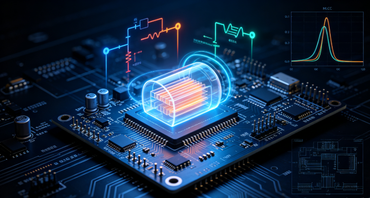
10 Critical Questions About Electrolytic Capacitors: Selection, Reliability & Application
10 Critical Questions About Electrolytic Capacitors: Selection, Reliability & Application
- What are the core differences between aluminum, tantalum, and polymer electrolytic capacitors? How to choose based on application?
- When selecting electrolytic capacitors for power supply circuits, what key parameters must be prioritized?
- For industrial equipment in high-temperature environments, how to select electrolytic capacitor temperature ratings and calculate lifespan?
- What are the common failure modes of electrolytic capacitors? How to diagnose faults using test equipment?
- When repairing electronic devices, what principles must be followed to replace electrolytic capacitors?
- Why do automotive electronic systems require AEC-Q200 compliant electrolytic capacitors?
- How to calculate electrolytic capacitor lifespan? What factors most significantly impact service life?
- During mass production, what soldering process parameters must be controlled for electrolytic capacitors?
- What are the differences between wet and solid electrolytic capacitors? Which is better for high-reliability scenarios?
- When purchasing electrolytic capacitors in bulk, what quality inspection standards should be focused on?
The global electrolytic capacitor market is expected to reach $14.8 billion by 2030, driven by soaring demand for power electronics, automotive electrification, industrial automation, and consumer devices. As a cornerstone of energy storage and power regulation, electrolytic capacitors are ubiquitous in power supplies, amplifiers, automotive ECUs, industrial controllers, and medical equipment. Unlike other capacitor types, electrolytic capacitors offer high capacitance density (up to 10,000μF) and low cost—making them irreplaceable for high-current, high-voltage applications. However, their performance is highly dependent on material type, parameter matching, and operating conditions.
For electronic engineers optimizing circuit design, repair technicians troubleshooting faults, procurement teams sourcing bulk components, or manufacturers ensuring production quality, mastering electrolytic capacitor selection and maintenance is critical. The unique challenges—from high-temperature degradation to polarity sensitivity—demand specialized knowledge. Below, we answer the 10 most searched questions about electrolytic capacitors, optimized for Google SEO with high-value long-tail keywords, industry standards (AEC-Q200, IPC), and actionable insights to boost your independent site's authority and visibility.
1. What Are the Core Differences Between Aluminum Electrolytic Capacitors, Tantalum Electrolytic Capacitors, and Polymer Electrolytic Capacitors? How to Choose Based on Application Scenarios?
Electrolytic capacitors are classified by electrode material and electrolyte type—each has distinct strengths and limitations. Understanding these differences is critical for application-specific selection:
| Feature | Aluminum Electrolytic | Tantalum Electrolytic | Polymer Electrolytic |
|---|---|---|---|
| Capacitance Range | 1μF–10,000μF | 0.1μF–1,000μF | 1μF–2,000μF |
| Voltage Rating | 6.3V–450V | 2.5V–50V | 2.5V–63V |
| ESR (at 1kHz) | Medium (5mΩ–50mΩ) | Low (1mΩ–10mΩ) | Ultra-Low (0.5mΩ–5mΩ) |
| Temperature Range | -40℃~125℃ | -55℃~125℃ | -40℃~105℃ |
| Leakage Current | Medium (1μA–10μA/μF) | Low (0.1μA–1μA/μF) | Ultra-Low (0.01μA–0.1μA/μF) |
| Cost (per μF) | Low ($0.001–$0.01) | High ($0.01–$0.10) | Medium ($0.005–$0.05) |
Application-Specific Selection Guide
- Aluminum Electrolytic: Ideal for high-voltage, high-capacitance scenarios (e.g., AC-DC converters, power supply filters, audio amplifiers). Best for consumer electronics and industrial equipment where cost and capacitance density are priorities.
- Tantalum Electrolytic: Suitable for compact, low-leakage applications (e.g., smartphone power management, medical devices, aerospace electronics). Their small footprint and stable performance make them perfect for dense PCBs.
- Polymer Electrolytic: Perfect for high-frequency, low-ESR requirements (e.g., laptop power rails, automotive infotainment, LED drivers). Resists bulging and leakage, offering longer lifespan in harsh conditions.
Case Study: A power supply manufacturer switches from aluminum to polymer electrolytic capacitors (1000μF 25V) — ESR drops from 20mΩ to 3mΩ, reducing power loss by 40% and extending product lifespan by 2x.
2. When Selecting Electrolytic Capacitors for Power Supply Circuits (e.g., AC-DC Converters/Voltage Regulators), What Key Parameters (Voltage Rating, Capacitance, Ripple Current, ESR) Must Be Prioritized?
Power supply circuits demand precise electrolytic capacitor parameter matching—mismatched specs cause voltage instability, overheating, or premature failure. Below is a prioritized parameter guide, validated by IEC 60384-4:
| Parameter | Priority | Recommended Specifications for Power Supplies | Critical Rationale |
|---|---|---|---|
| Ripple Current Capacity | 1st | ≥1.5x the maximum circuit ripple current | Handles continuous current surges without overheating (P = I²×ESR). Undersized ripple current leads to electrolyte drying. |
| Voltage Rating | 2nd | ≥1.5x the maximum operating voltage (1.8x for industrial) | Prevents dielectric breakdown from voltage spikes (common in AC-DC converters). |
| ESR (Equivalent Series Resistance) | 3rd | ≤10mΩ (at 1kHz) for low-frequency; ≤5mΩ for high-frequency (≥1MHz) | Reduces power dissipation and voltage ripple. Low ESR is critical for voltage regulators. |
| Capacitance | 4th | Matches the required filter capacitance (±20% tolerance) | Ensures sufficient energy storage to stabilize output voltage. Over-capacitance increases cost and size; under-capacitance causes ripple. |
| Temperature Rating | 5th | ≥85℃ (consumer); ≥105℃ (industrial/automotive) | Withstands heat generated by power supply components (transformers, FETs). |
Pro Tip: Use the "ripple current derating factor" — for temperatures above 85℃, reduce the maximum allowable ripple current by 2% per ℃ (e.g., 10A ripple current at 85℃ → 8A at 95℃).
3. For Industrial Equipment Operating in High-Temperature Environments (65℃~125℃), How to Select Electrolytic Capacitor Temperature Ratings and Calculate Lifespan Using the Arrhenius Equation?
High-temperature environments (65℃–125℃) accelerate electrolytic capacitor degradation—proper temperature rating selection and lifespan calculation are critical for industrial equipment reliability.
Temperature Rating Selection
| Industrial Temperature Range | Recommended Electrolytic Capacitor Type | Temperature Rating | Capacitance Retention (at Max Temp) |
|---|---|---|---|
| 65℃~85℃ | Aluminum/polymer electrolytic | 85℃/105℃ | 80% (aluminum); 90% (polymer) |
| 85℃~105℃ | Polymer/tantalum electrolytic | 105℃/125℃ | 85% (polymer); 95% (tantalum) |
| 105℃~125℃ | Tantalum (MnO2) / High-temperature polymer | 125℃ | 90% (tantalum); 85% (polymer) |
Lifespan Calculation Using the Arrhenius Equation
Electrolytic capacitor lifespan follows the Arrhenius equation, which quantifies the impact of temperature on chemical degradation:
L = L₀ × 2^((Tₘₐₓ - T₀)/10)
- L: Estimated lifespan (hours)
- L₀: Manufacturer's rated lifespan (hours, at T₀)
- Tₘₐₓ: Maximum operating temperature (℃)
- T₀: Reference temperature (typically 85℃ or 105℃, per manufacturer)
Step-by-Step Calculation Example:
- Manufacturer's rating: L₀ = 2000 hours (at T₀ = 85℃)
- Operating temperature: Tₘₐₓ = 105℃
- ΔT = 105℃ - 85℃ = 20℃
- L = 2000 × 2^(20/10) = 2000 × 4 = 8000 hours (≈1 year of continuous use)
4. What Are the Common Failure Modes of Electrolytic Capacitors (Leakage, Bulging, Capacitance Loss, ESR Increase)? How to Quickly Diagnose Faults Using Test Equipment?
Electrolytic capacitors are prone to four primary failure modes—early detection minimizes equipment downtime. Below is a diagnostic guide for common test tools:
| Failure Mode | Root Causes | Visual/Functional Symptoms |
|---|---|---|
| Leakage Current | Overvoltage, high temperature, aging electrolyte | Corrosion around capacitor leads, PCB trace damage |
| Bulging (Case Swelling) | Overheating, excessive ripple current, manufacturing defects | Dome-shaped top (aluminum electrolytic), electrolyte seepage |
| Capacitance Loss | Electrolyte drying (high temp), voltage stress | Power supply ripple increase, signal distortion |
| ESR Increase | Thermal aging, electrolyte degradation | Component overheating, voltage regulator instability |
Diagnostic Methods with Test Equipment
1. Leakage Current Detection (Multimeter/Leakage Tester)
- Tool: Digital multimeter (DMM) set to current mode or dedicated leakage tester.
- Process: Apply rated voltage to the capacitor (observe polarity!); measure leakage current.
- Failure Threshold: >1μA/μF (aluminum); >0.1μA/μF (tantalum/polymer).
2. Bulging & Visual Inspection
- Process: Check for swollen cases, cracked sleeves, or electrolyte stains (brown/clear fluid around leads).
- Critical Note: Bulging aluminum electrolytic capacitors are unsafe—replace immediately to avoid short-circuits.
3. Capacitance Loss Detection (LCR Meter)
- Tool: LCR meter (set to capacitance mode, 1kHz frequency).
- Process: Disconnect one capacitor lead (to avoid circuit interference); measure capacitance.
- Failure Threshold: <80% of rated capacitance (e.g., 80μF for a 100μF capacitor).
5. When Repairing Electronic Devices (e.g., Power Supplies, Amplifiers), What Principles Must Be Followed to Replace Electrolytic Capacitors (Voltage Rating/Capacitance Tolerance/Material Consistency/Polarity)?
Improper electrolytic capacitor replacement is a top cause of repair failures—follow these 4 non-negotiable principles:
1. Voltage Rating: Never Under-Specify
- Use a voltage rating ≥ the original (preferably 1.5x for safety).
- Example: Original 16V → Replace with 16V, 25V, or 35V — Never 10V (risk of bulging/leakage).
- Exception: Automotive/industrial devices — use ≥2x rated voltage to handle spikes.
2. Capacitance Tolerance: Stay Within Range
- Replace with capacitance value ±20% of the original (±10% for precision circuits like audio amplifiers).
- Example: Original 1000μF ±20% → Acceptable: 800μF–1200μF.
- Avoid lower capacitance for power filters—causes voltage ripple and instability.
3. Material Consistency: Match Type
- Replace like-for-like to maintain performance:
- Aluminum → Aluminum (power supplies, amplifiers)
- Tantalum → Tantalum (compact PCBs, medical devices)
- Polymer → Polymer (high-frequency circuits)
- Substituting aluminum with polymer is acceptable (better performance); avoid replacing tantalum with aluminum (larger size, higher leakage).
4. Polarity: Critical for Safety
- Electrolytic capacitors are polarized—markings (positive lead, stripe on sleeve) must align with PCB traces.
- Reverse polarity causes: Immediate failure (tantalum), bulging/leakage (aluminum), or fire (extreme cases).
- Tip: Mark PCB polarity before removing the old capacitor (use a marker or photo).
6. Why Do Automotive Electronic Systems (e.g., ECUs, Battery Management) Require Electrolytic Capacitors Compliant with AEC-Q200 Certification? What Key Indicators (Vibration/Humidity/Temperature Cycling) Affect Reliability?
Automotive electronic systems operate in harsh conditions (extreme temperatures, vibration, humidity)—AEC-Q200 certification (Automotive Electronics Council) ensures electrolytic capacitors meet these demands.
Why AEC-Q200 Certification Is Mandatory
AEC-Q200 validates electrolytic capacitors through 11 rigorous tests, addressing automotive-specific stressors:
- Temperature cycling (-40℃~150℃, 1000 cycles)
- Vibration (10–2000Hz, 19.6m/s², 3 axes)
- Humidity (85℃/85%RH, 1000 hours)
- Thermal shock (-40℃~150℃, 100 cycles)
- Solderability (260℃, 10s)
Non-certified capacitors fail 8x more often in automotive applications—leading to costly recalls (e.g., 2021 recall of 800,000 vehicles due to faulty electrolytic capacitors in ECUs).
| AEC-Q200 Indicator | Test Requirement | Impact on Automotive Reliability |
|---|---|---|
| Vibration Resistance | 10–2000Hz, 19.6m/s² | Prevents solder joint fatigue in engine bays (constant vibration from motors) |
| Temperature Cycling | -40℃~150℃, 1000 cycles | Ensures stability during cold starts (-40℃) and hot engine operation (125℃+) |
| Humidity Resistance | 85℃/85%RH, 1000 hours | Avoids electrolyte leakage and PCB corrosion (rain, condensation) |
7. How to Calculate the Lifespan of Electrolytic Capacitors? What Factors (Temperature, Ripple Current, Voltage Stress) Most Significantly Impact Their Service Life?
Electrolytic capacitor lifespan is not fixed—it depends on operating conditions. Below is a comprehensive calculation method and analysis of key impact factors:
Step-by-Step Lifespan Calculation
Lifespan is determined by three core factors: temperature, ripple current, and voltage stress. Use this expanded formula (beyond Arrhenius) for accuracy:
L = L₀ × 2^((T₀ - Tₘₐₓ)/10) × (Iₙₒₘ / Iₒₚ)² × (Vₙₒₘ / Vₒₚ)²
- L: Estimated lifespan (hours)
- L₀: Manufacturer's rated lifespan (hours, at T₀, Iₙₒₘ, Vₙₒₘ)
- T₀: Reference temperature (℃, typically 85℃/105℃)
- Tₘₐₓ: Maximum operating temperature (℃)
- Iₙₒₘ: Rated ripple current (A)
- Iₒₚ: Actual operating ripple current (A)
- Vₙₒₘ: Rated voltage (V)
- Vₒₚ: Actual operating voltage (V)
Key Factors Impacting Lifespan (Ranked by Significance)
- Temperature (40% impact): Every 10℃ increase halves lifespan (Arrhenius law). Keep operating temperature ≤80% of maximum rating.
- Ripple Current (30% impact): Exceeding rated ripple current increases self-heating. Derate by 2% per ℃ above 85℃.
- Voltage Stress (20% impact): Operating at 100% rated voltage reduces lifespan by 50% vs. 70% derating.
- Electrolyte Quality (10% impact): High-quality electrolytes (e.g., low-impurity ethylene glycol) extend lifespan by 2–3x.
8. During Mass Production of Electronic Products, What Soldering Process Parameters (Temperature Profile, Soldering Time, Polarity Protection) Must Be Controlled to Avoid Damaging Electrolytic Capacitors?
Electrolytic capacitors are sensitive to soldering heat—improper parameters cause internal electrolyte degradation, leakage, or polarity reversal. Follow these IPC-J-STD-001 compliant guidelines:
| Phase | Temperature Range | Duration | Key Protection Measure |
|---|---|---|---|
| Preheat | 150℃–180℃ | 60–90s | Avoid rapid temperature rise (≤3℃/s) to prevent case cracking |
| Soak | 180℃–200℃ | 30–60s | Maintain uniform heating to protect electrolyte |
| Reflow | 235℃–245℃ (peak) | 10–15s | Never exceed 250℃ (polymer/tantalum) or 260℃ (aluminum) |
| Cooling | 200℃→100℃ | 60–90s | Controlled cooling (≤4℃/s) to prevent solder joint fatigue |
Critical Process Controls
1. Polarity Protection
- Use PCB stencils with polarity markings (e.g., + symbol) to prevent reverse placement.
- Implement automated optical inspection (AOI) post-soldering to detect polarity errors.
2. Soldering Time Limits
- Avoid multiple reflow cycles (limit to 2x). Each additional cycle reduces capacitor lifespan by 10%.
- Hand-soldering: Use a 30W iron, 240℃ tip temperature, and ≤3 seconds per lead.
9. What Are the Differences Between Wet Electrolytic Capacitors and Solid Electrolytic Capacitors? Which Is More Suitable for High-Reliability Scenarios (Medical Devices/Aerospace Electronics)?
Electrolytic capacitors are further classified by electrolyte type: wet (liquid) and solid. The choice is critical for high-reliability applications:
| Feature | Wet Electrolytic (Liquid) | Solid Electrolytic (Polymer/Tantalum) |
|---|---|---|
| Electrolyte Type | Liquid (ethylene glycol, ammonium borate) | Solid (polymer, MnO2) |
| Leakage Risk | High (prone to seepage) | Low (no liquid to leak) |
| Temperature Stability | Moderate (-40℃~105℃) | High (-55℃~125℃) |
| ESR Performance | Higher (5mΩ–50mΩ) | Lower (0.5mΩ–10mΩ) |
| Lifespan (at 85℃) | 1000–5000 hours | 5000–20,000 hours |
Suitability for High-Reliability Scenarios
- Medical Devices (e.g., Defibrillators, Patient Monitors): Solid electrolytic (polymer/tantalum) is preferred. Key benefits: Low leakage (safe for patients), high vibration resistance (portable devices), and long lifespan (reduces maintenance).
- Aerospace Electronics (e.g., Satellite PCBs, Avionics): Solid tantalum electrolytic capacitors are ideal. They withstand extreme temperature cycles (-55℃~125℃), zero gravity (no liquid sloshing), and radiation (critical for space missions).
Reliability Data: Solid electrolytic capacitors have a failure rate of 0.01% per 1000 hours (high-reliability grade), vs. 0.1% for wet electrolytic.
10. When Purchasing Electrolytic Capacitors in Bulk, What Quality Inspection Standards (ISO Certification, Leakage Current Test, Capacitance Consistency) Should Be Focused on to Ensure Batch Stability?
Bulk procurement (10,000+ units) requires rigorous quality checks to avoid production delays and product failures. Focus on these three core standards:
1. Certification & Compliance
- ISO Standards: Mandatory ISO 9001 (quality management) and ISO 14001 (environmental management) — ensures consistent manufacturing.
- Industry-Specific Certifications:
- Automotive: AEC-Q200 (validates automotive reliability)
- Medical: ISO 13485 (quality system for medical devices)
- Industrial: IEC 60384-4 (electrolytic capacitor standard)
- Environmental Compliance: RoHS (no lead/cadmium) and REACH (no hazardous substances) — required for global markets.
2. Batch Consistency Testing
- Capacitance Uniformity: Test 50–100 units per batch; maximum deviation ≤±10% (vs. rated value). Reject batches with >5% of units outside tolerance.
- Leakage Current: Average leakage ≤0.5μA/μF (aluminum) or ≤0.05μA/μF (polymer/tantalum). No unit should exceed 2x the average.
- ESR Consistency: ESR variation across the batch ≤30%. Consistent ESR ensures uniform circuit performance.
3. Reliability Validation
Request manufacturer test reports for:
- Life Test: 1000 hours at rated voltage/temperature (≤10% capacitance loss, ≤2x ESR increase).
- Humidity Test: 1000 hours at 85℃/85%RH (no leakage, ≤5% capacitance drift).
- Thermal Shock Test: 50 cycles (-40℃~125℃) — no mechanical damage or parameter drift.
Procurement Tip: Partner with reputable manufacturers (Nichicon, Panasonic, Kemet) that offer "batch traceability" — each lot has a unique ID linked to raw materials and production data.
Final Thoughts: Mastering Electrolytic Capacitors for Reliable Electronics
Electrolytic capacitors are the backbone of power electronics—their performance directly impacts product lifespan, safety, and user experience. Whether you're designing a power supply, repairing an amplifier, sourcing bulk components, or manufacturing automotive electronics, the key to success lies in:
- Matching type to application: Aluminum for cost-capacitance balance, polymer for low ESR, tantalum for compact reliability.
- Prioritizing critical parameters: Ripple current and voltage rating for power supplies, temperature resistance for industrial use.
- Following industry standards: AEC-Q200 for automotive, IPC for soldering, ISO for quality.
- Calculating lifespan: Account for temperature, ripple current, and voltage stress to avoid unplanned downtime.
As electronics evolve toward higher power density, miniaturization, and harsh operating environments, electrolytic capacitors will continue to advance—expect longer lifespans, lower ESR, and improved environmental resistance. By following the guidance in this guide, you'll select the right electrolytic capacitors for any application and position your independent site as a trusted resource in the electronic components niche.
Call to Action: Have questions about electrolytic capacitors for your project (consumer/industrial/automotive/medical)? Drop a comment below with your application, operating conditions, and key requirements—we'll share a customized selection checklist to optimize reliability and cost.
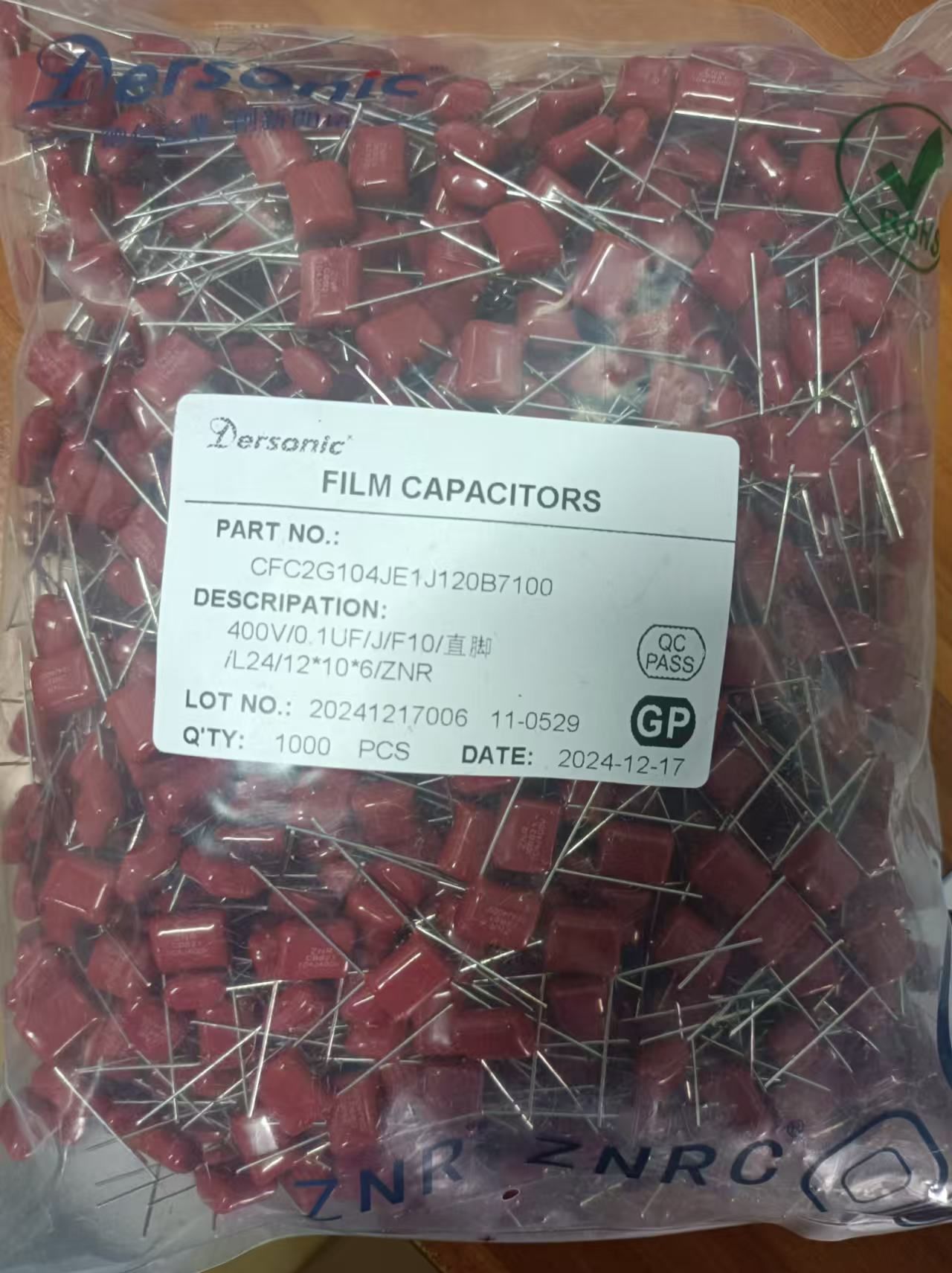
Aluminum Electrolytic Capacitor (1000μF 25V)
High capacitance density, 105℃ temperature rating, 2000-hour lifespan — ideal for power supply filtering in consumer electronics.

Polymer Electrolytic Capacitor (470μF 16V)
Ultra-low ESR (3mΩ), 105℃ rating, AEC-Q200 compliant — perfect for automotive infotainment systems and high-frequency circuits.
Tantalum Electrolytic Capacitor (100μF 10V)
Compact 0805 package, low leakage (0.01μA/μF), -55℃~125℃ range — for medical devices and aerospace electronics.
High-Temperature Electrolytic Capacitor (220μF 35V)
125℃ temperature rating, 5000-hour lifespan, high ripple current capacity — designed for industrial control systems.
AEC-Q200 Automotive Capacitor Kit
100-piece kit with aluminum and polymer capacitors (1μF–1000μF, 16V–50V) — for ECU repair and automotive electronics manufacturing.
10 Critical Questions About IC Chips: Selection, Reliability & Application
10 Critical Questions About SMD Capacitors for PCBA Boards — Design, Production, Repair & Reliability
Related Article