Understanding MLCC ESR and ESL High Frequency Impedance Characteristics in Decoupling Design
Understanding MLCC ESR and ESL: High‑Frequency Impedance Characteristics in Decoupling Design
Email: hyc2355937758@gmail.com
WhatsApp: +86 15913754866
Tel: +86 18824523083
Website: barronmlcc.com
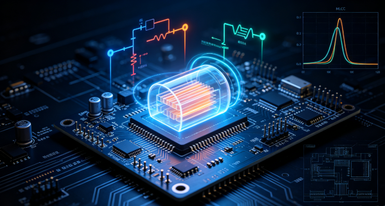
When electrical and hardware design engineers analyze Multi‑Layer Ceramic Capacitors (MLCCs) on paper, they often treat them as ideal components defined solely by their nominal capacitance value. In real‑world high‑frequency circuits, however, a capacitor behaves more like a complex RLC circuit.
To successfully design low‑impedance power distribution networks (PDN) and filter high‑speed digital noise, engineers must account for two critical parasitic properties: Equivalent Series Resistance (ESR) and Equivalent Series Inductance (ESL).
1. Dissecting the Real Impedance of an MLCC
An actual manufactured MLCC includes not just the capacitive dielectric layers, but also the resistance of the internal electrode plates and outer terminations, as well as the inductive loop created by current flowing through the component body. This gives rise to three distinct impedance contributors:
- Capacitance ($C$): Dominates at low frequencies, where impedance decreases inversely as frequency rises ($X_c = 1 / 2\pi f C$).
- Equivalent Series Resistance (ESR): Represents the total resistive losses within the capacitor, encompassing dielectric losses, terminal resistance, and electrode resistance. At the capacitor's self‑resonant frequency, ESR forms the absolute minimum floor of the impedance curve.
- Equivalent Series Inductance (ESL): Arises from the physical dimensions of the component and current path geometry. At frequencies above self‑resonance, ESL takes over, causing the capacitor's impedance to rise again like an inductor ($X_L = 2\pi f L$).
2. The Significance of Self‑Resonant Frequency (SRF)
The interplay between capacitance and ESL creates a V‑shaped impedance curve known as the Self‑Resonant Frequency (SRF).
At SRF: The capacitive reactance and inductive reactance cancel each other out completely. At this specific frequency, the MLCC achieves its lowest possible impedance, making it a highly efficient noise filter.
Above SRF: The component ceases to act as a capacitor. Instead, it behaves inductively, meaning high‑frequency noise can pass right through it unmitigated. This is why selecting smaller case sizes (which feature lower ESL) is vital for high‑speed microprocessors and FPGAs.
3. Engineering Implications for High‑Speed Circuit Design
Package Size Dictates ESL: Physical case size directly impacts parasitic inductance. Miniature packages (such as 0402 and 0201) possess shorter current paths and lower internal loops, resulting in a higher SRF compared to larger packages (like 1206 or 1210).
Targeted Decoupling Arrays: Because no single MLCC exhibits low impedance across all frequencies, high‑performance designs deploy parallel arrays combining bulk capacitors (for low frequencies) with ultra‑small, low‑ESL ceramic capacitors placed directly adjacent to high‑speed IC power pins.
Source High‑Performance MLCCs with Optimized Impedance Profiles
Ensure your high‑speed circuit designs achieve ultra‑low PDN impedance and robust noise suppression with precision surface‑mount components from barronmlcc.com. We provide complete technical datasheets, impedance curves, and reliable wholesale supply solutions. Contact our technical sales engineering team today for expert BOM cross‑referencing and custom quotations.
Direct Email: hyc2355937758@gmail.com
WhatsApp & Mobile: +86 15913754866
Telephone Support: +86 18824523083
Official Web Portal: //www.barronmlcc.com
Understanding MLCC ESR and ESLHigh Frequency Impedance Characteristics in Decoupling Design
MLCC Capacitor Soldering 6 Common Problems and How to Avoid Them
Related Article
