MLCC Capacitor Soldering 6 Common Problems and How to Avoid Them
MLCC Capacitor Soldering: 6 Common Problems and How to Avoid Them
MLCC capacitors are widely used in modern electronic products, but incorrect soldering can affect their performance and reliability. Problems may include poor solder joints, component movement, thermal stress, and ceramic cracks. These issues can lead to production defects or failures after assembly. Whether you manufacture consumer electronics, industrial equipment, or automotive electronics, understanding the basic soldering requirements can help reduce unnecessary risks.
1. Why Is MLCC Soldering Important?
An MLCC contains multiple thin ceramic and metal layers. Although the component is designed for electronic assembly, its ceramic body can be damaged by excessive thermal or mechanical stress. During reflow soldering, the capacitor heats up and cools down as part of the PCB assembly process. If the temperature changes too quickly or the process is poorly controlled, stress may develop inside the component. Following the manufacturer's recommended soldering profile is therefore an important step in protecting component reliability.
2. Problem One: Thermal Shock
Thermal shock can occur when an MLCC experiences a sudden temperature change, such as when a relatively cold component is exposed to excessive heat too quickly. This can create internal stress and, in some cases, cracks. To reduce the risk, use a controlled heating and cooling profile and follow the recommended temperature limits for the specific MLCC and soldering materials. Avoid applying a soldering iron directly to the ceramic body, and do not assume that every capacitor package can use exactly the same process settings.
3. Problem Two: Uneven Soldering and Tombstoning
Tombstoning happens when a small surface‑mount component stands up on one end during reflow soldering. It can occur when the two solder joints heat or melt unevenly, creating an unbalanced force on the component. Common factors include PCB pad design, solder paste volume, component placement, and differences in heating across the board. To reduce tombstoning, review the land pattern, keep solder paste deposition consistent, check component placement accuracy, and optimize the reflow profile. The correct solution depends on the PCB design and assembly process.
4. Problem Three: Poor Solder Joints
Insufficient solder, contamination, unsuitable solder paste, or an incorrect temperature profile can result in weak or incomplete solder joints. These defects may cause intermittent electrical connections or assembly failures. During production, inspect solder joints using suitable methods such as automated optical inspection (AOI), where appropriate. Ensure that the PCB pads and component terminations are compatible with the selected soldering process. If a defect appears repeatedly, investigate the assembly conditions rather than simply replacing the affected capacitors.
5. Problem Four: Mechanical Stress After Soldering
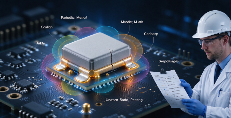
An MLCC can be damaged even when the soldering process itself appears normal. PCB depanelization, board bending, connector insertion, screw tightening, and other mechanical operations can transfer stress to the ceramic component. Cracks may not always be visible during a quick visual inspection. To reduce risk, avoid placing MLCCs near board edges, mounting holes, and high‑stress areas when possible. Use suitable depanelization methods and follow good PCB handling practices. For applications with higher mechanical stress, consider whether an MLCC with flexible or soft terminations is appropriate.
6. How Can Manufacturers Improve MLCC Soldering Quality?
A reliable process starts with the component datasheet and the PCB assembly requirements. Confirm the recommended reflow profile, solder paste, pad layout, package size, and inspection method before mass production. Test the assembly process with sample boards and check for component movement, solder defects, and possible cracks. If the product operates in a demanding environment, additional electrical or reliability testing may be necessary. Good process control helps identify problems early and reduces the risk of repeated production defects.
Conclusion
MLCC soldering problems can result from thermal shock, uneven heating, poor solder joints, or mechanical stress during later assembly steps. The best way to reduce these risks is to control the soldering process, use an appropriate PCB layout, handle boards carefully, and validate the process before mass production.
If you are sourcing MLCC capacitors for your electronic products, selecting the correct package and component specifications is only part of the process. Share your part number, package size, application, and required quantity with our team to discuss suitable options for your project.
Contact Us
Email: hyc2355937758@gmail.com
WhatsApp: +86 15913754866
Tel: +86 18824523083
Website: www.barronmlcc.com
MLCC vs Electrolytic Capacitor Which One Is Better for Your Circuit
Related Article