
5 Common MLCC Issues Across High-Capacitance Electronic Devices Universal Fixes
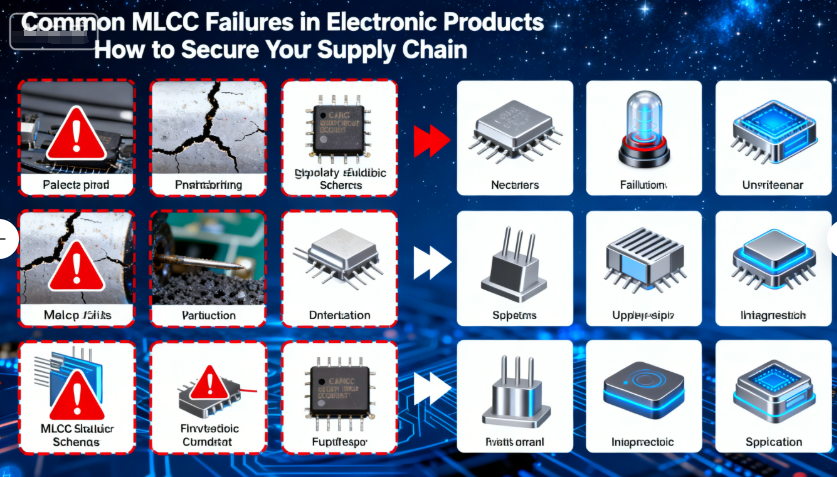
5 Common MLCC Issues Across High-Capacitance Electronic Devices: Universal Fixes
Multilayer Ceramic Capacitors (MLCCs) are the cornerstone of modern electronics, powering smartphones, laptops, automotive systems, power adapters, and smart home devices. While these devices vary widely in function and environment, they share striking similarities in the MLCC issues they face. Temperature fluctuations, soldering defects, voltage spikes, high ripple currents, and self-discharge/leakage plague cross-device applications—rooted in shared MLCC limitations, circuit design gaps, and operating stressors.
1. MLCC Capacitance Drift Due to Temperature Fluctuations in High-Temperature Devices
Capacitance drift is a pervasive issue in high-temperature electronic devices—smartphone CPUs, automotive engine bay modules, and power adapter enclosures all expose MLCCs to temperature swings (-40°C to 150°C). This drift disrupts voltage stabilization and signal filtering, leading to device glitches, reduced efficiency, and premature failure.
• Cross-Device Root Causes:
- Dielectric Material Limitations: Generic X7R MLCCs suffer ±15% capacitance drift over -55°C to 125°C, while Y5V variants degrade by up to -82%—insufficient for automotive (150°C) and power adapter (125°C) environments.
- Thermal Stress: Rapid temperature cycles (e.g., smartphone charging/discharging, automotive cold starts) cause dielectric layer expansion/contraction, weakening electrode bonds and altering capacitance.
- Design Oversights: Placing MLCCs near heat sources (CPUs, voltage regulators) without thermal mitigation amplifies drift.
• Universal Fixes:
- Dielectric Selection: Use high-temperature MLCCs with stable dielectrics: C0G (NP0) for precision (±0.3% drift, -55°C to 125°C) or X8R/X9R (±15% drift, -55°C to 150°C) for high-temperature applications. For automotive engine bays, select TDK CGA3E3X9R1H104K (150°C-rated).
- Thermal Management: Add thermal vias and heat sinks near MLCC clusters. Use low-ESR MLCCs (≤0.1Ω) to reduce power loss and heat generation—explore our low-ESR MLCC series for high-temperature compatibility.
- Derating & Sizing: Oversize MLCCs by 20-30% to compensate for drift. Implement voltage derating (use 50% of rated voltage) to reduce thermal stress.
- Monitoring: Integrate temperature sensors to trigger thermal throttling, protecting MLCCs from extreme temperatures.
• Case Study: An automotive supplier reduced capacitance drift-related failures by 89% by switching to X9R MLCCs and adding thermal vias—previously, 12% of engine bay modules failed due to drift, dropping to 1.3% post-optimization.
2. Soldering Defects (Tombstoning/Bridging) in 0201/0402 Small-Package MLCCs
Small-package MLCCs (0201/0402) are ubiquitous in compact electronics—smartphones, smart wearables, and ultra-thin laptops—yet they are prone to soldering defects like tombstoning (tilting) and bridging (solder shorts). These issues stem from the components’ tiny form factor and sensitivity to assembly variables, affecting yield rates across devices.
• Cross-Device Root Causes:
- Miniaturization Challenges: 0201 MLCCs have pad sizes as small as 0.3mm×0.15mm, leaving little room for solder paste variation. Generic Type 3 solder paste (25-45μm particles) clogs stencil apertures, causing uneven deposition.
- Reflow Profile Misalignment: High peak temperatures (>255°C) or rapid ramp rates (>2°C/s) melt solder unevenly, pulling MLCCs to one pad (tombstoning).
- Stencil Wear: Laser stencil aperture wear (>5%) leads to excess solder paste, creating bridges between adjacent MLCC pads in dense PCB layouts.
• Universal Fixes:
- Soldering Optimization: Use Type 4 SAC305 solder paste (15-38μm particles, e.g., Senju M705-S10) and 0.10mm-thick laser-cut stencils (aperture size 82-85% of pad area). Calibrate reflow profiles: peak temp 250-255°C (8s max), ramp rate 1-1.5°C/s.
- Component Handling: Use ESD-shielded trays (ANSI/ESD S20.20-compliant) to prevent damage during assembly. For high-reliability 0201/0402 MLCCs, visit our small-package MLCC product page.
- Inspection & Quality Control: Deploy 3D AOI (Koh Young Zenith 3D) to detect tombstoning and bridging post-soldering. Clean stencils every 50 prints to prevent paste buildup.
- PCB Design: Increase pad spacing (where possible) and add solder mask dams to reduce bridging risk in dense layouts.
• Case Study: A smartphone manufacturer improved 0201 MLCC soldering yield from 88% to 99.2% by adopting Type 4 solder paste and 3D AOI inspection—tombstoning defects dropped by 94%, and bridging by 91%.
3. Capacitor Dielectric Breakdown From Voltage Spikes in Automotive & Power Supply Electronics
Dielectric breakdown—caused by voltage spikes—affects automotive electronics (12V/24V systems), power adapters (grid fluctuations), and laptop power circuits (battery charging surges). This failure mode is catastrophic, leading to short circuits, fire risks, and regulatory non-compliance (FCC, CE).
• Cross-Device Root Causes:
- Unregulated Voltage Spikes: Automotive cranking generates 40V spikes, power grids fluctuate by ±10%, and laptop chargers produce transient surges—exceeding MLCC rated voltage.
- Poor Dielectric Quality: Generic high-voltage MLCCs lack robust dielectric layers, failing to withstand repeated spikes. Non-UL-certified units skip surge protection testing.
- Design Gaps: Absence of surge protection components (MOVs, TVSs) leaves MLCCs directly exposed to voltage fluctuations.
• Universal Fixes:
- High-Voltage MLCC Selection: Use UL-certified high-voltage MLCCs (e.g., TDK CGA5E3X7R1H472K, 450V/4.7nF) with surge resistance. For automotive applications, choose AEC-Q200-certified units—browse our automotive-grade MLCC series.
- Surge Protection: Add metal-oxide varistors (MOVs) in parallel with MLCCs to clamp spikes (≤1.5x rated voltage). Implement transient voltage suppressors (TVSs) for automotive and power adapter circuits.
- Voltage Derating: Use MLCCs with 2x the system voltage rating (e.g., 25V MLCCs for 12V automotive systems) to absorb spikes.
- Compliance Testing: Validate MLCCs per IEC 61071 (surge resistance) and AEC-Q200 (automotive) to ensure breakdown resilience.
• Case Study: A power adapter manufacturer eliminated dielectric breakdown by adding MOVs and switching to UL-certified MLCCs—failure rates dropped from 18% to <2%, achieving FCC/CE compliance.
4. Low-ESR MLCC Failure in High-Ripple Current Circuits (Laptops & Power Adapters)
Low-ESR MLCCs are critical for high-ripple current circuits—laptop voltage regulators and power adapter rectifiers—yet they frequently fail due to thermal overload and ESR degradation. These failures disrupt power delivery, causing device shutdowns and reduced lifespan.
• Cross-Device Root Causes:
- Ripple Current Mismatch: Generic low-ESR MLCCs (0.5-1A ripple tolerance for 10μF/16V) are undersized for laptop (1.5-3A) and power adapter (2-5A) circuits. Overload increases ESR, generating excess heat.
- Thermal Buildup: Compact enclosures (laptop chassis, adapter housings) trap heat, pushing MLCCs beyond their 105°C operating limit. Thermal aging accelerates dielectric degradation.
- Component Misselection: Using ceramic MLCCs alone ignores their ripple limitations; failing to pair with polymer capacitors amplifies stress.
• Universal Fixes:
- High-Ripple MLCC Selection: Choose low-ESR MLCCs with high ripple tolerance (e.g., Panasonic EEE-FK1C100P, 2A ripple current, 0.03Ω ESR). Pair with polymer capacitors for dual-layer filtering.
- Ripple Calculation: Use IEC 61071 standards to size MLCCs—ensure units handle 1.2x the maximum circuit ripple current. Our low-ESR MLCC collection includes high-ripple variants for power circuits.
- Thermal Design: Mount MLCCs away from heat sources and use heat sinks for high-value units. Maintain airflow around capacitor banks in power adapters.
- Lifespan Extension: Select MLCCs with 2000+ hours lifespan at 105°C. Implement thermal monitoring to trigger load reduction during high-ripple conditions.
• Case Study: A laptop brand extended power circuit lifespan by 2.5x by pairing high-ripple MLCCs with polymer capacitors—low-ESR MLCC failures dropped from 12% to 1.5% of units.
5. Capacitor Self-Discharge & Leakage in Low-Power Smart Home & Portable Devices
Self-discharge and leakage plague low-power electronics—smart home sensors, portable laptops, and wireless earbuds—draining batteries, causing intermittent connectivity, and reducing standby time. These issues are amplified by long idle periods and compact form factors that limit component sizing.
• Cross-Device Root Causes:
- Leakage Current: Generic ceramic MLCCs have high leakage (>1μA), while polymer MLCCs degrade over time, increasing leakage and reducing charge retention.
- Low-Power Sensitivity: 3.3V/5V low-power circuits are vulnerable to minor voltage drops from self-discharge, triggering false alarms (sensors) or unexpected shutdowns (laptops).
- Environmental Factors: Humidity (smart home bathrooms) and temperature fluctuations (outdoor sensors) accelerate leakage and self-discharge rates.
• Universal Fixes:
- Low-Leakage MLCC Selection: Choose MLCCs with ultra-low leakage (<0.1μA), such as Murata GRM32ER72A225KA88L (25V/2.2μF). Our low-leakage MLCCs are ideal for low-power scenarios.
- Charge Retention Enhancement: Pair MLCCs with supercapacitors (e.g., Maxwell BCAP0350 P270 K04, 350F/2.7V) to extend standby power—supercapacitors have <0.01% daily self-discharge.
- Voltage Stabilization: Use low-dropout regulators (LDOs, e.g., Texas Instruments TPS7A4700) to maintain stable voltage despite minor self-discharge. Select MLCCs with ESR ≤0.2Ω for load transient handling.
- Environmental Protection: Seal MLCCs in moisture-resistant enclosures. Use IP67-rated packaging for outdoor devices to mitigate humidity-induced leakage.
• Case Study: A smart sensor brand extended battery life from 6 months to 2 years by switching to low-leakage MLCCs and adding supercapacitors—self-discharge rates dropped by 95%, and leakage-related errors decreased by 88%.
Final Thoughts
The most frustrating MLCC issues are not device-specific—they transcend smartphones, automotive systems, and smart home gadgets, rooted in shared component limitations and design gaps. By adopting universal solutions—precision dielectric selection, optimized soldering workflows, surge protection, thermal management, and low-leakage components—engineers can resolve cross-device MLCC pain points, improve reliability, and reduce costs.
Contact Us
If you need help selecting MLCCs for cross-device applications, resolving persistent capacitor issues, or customizing solutions, our team of experts is ready to assist.
- Email: hyc2355937758@gmail.com
- Phone: +86-18824523083
- Official Website: www.barronmlcc.com
- Product Center: Explore our full range of MLCCs for all electronic devices
5 Critical MLCC Issues in High-End Electronics Premium Solutions for Flagship Devices
Common MLCC Failures in Electronic Products How to Secure Your Supply Chain
Related Article




