
High Voltage DC MLCC Specialization Dielectric Breakdown Voltage Bias Characteristics Creepage Insulation Design Derating Specifications High-Voltage Reliability Verification
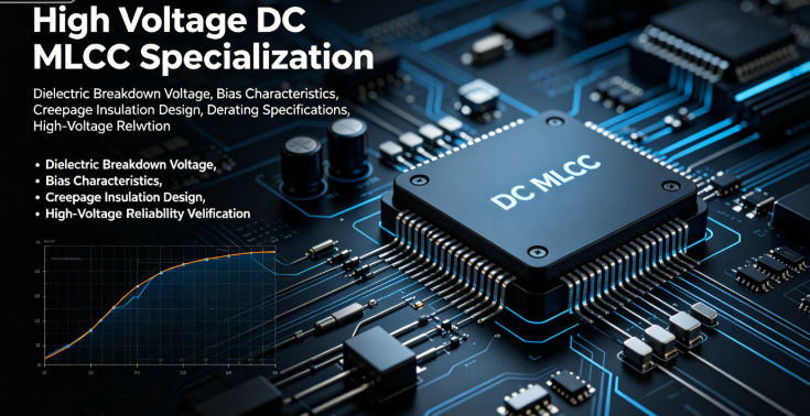
High-Voltage DC MLCC Specialization: Dielectric Breakdown, Voltage Bias Characteristics, Creepage & Insulation Design, Derating Specifications & High-Voltage Reliability Verification
Company: Dongguan Musen Laidun Electronic Technology Co., Ltd.
Keywords: High-Voltage MLCC, High-Voltage DC Capacitor, Dielectric Breakdown, Voltage Bias Characteristics, Creepage Distance, High-Voltage Derating Standard, PV Energy Storage, EV Charger High-Voltage Circuit
mu sen Introduction
In new energy PV, energy storage systems, EV chargers, industrial inverters, high-voltage security power supplies, and high-power DC-DC converters, high-voltage DC MLCCs have become indispensable core passive components. Compared to standard low-voltage MLCCs, failure mechanisms under high voltage are completely different: low-voltage failures mostly involve mechanical cracking, noise, or moisture leakage; while high-voltage MLCC failures concentrate on five critical issues: DC bias capacitance collapse, dielectric chronic breakdown, high-voltage creepage arcing, ion migration, and thermal runaway short circuits.
Currently, many engineers hold common design misconceptions: selecting components solely by rated voltage, ignoring Class II dielectric high-voltage bias attenuation, neglecting PCB creepage distances, and substituting standard MLCCs for specialized high-voltage types. These errors cause massive short circuits, system burnout, and warranty claims 3–6 months after mass production—major reliability pain points in the high-voltage power industry.
Based on IEC 60384, IPC/JEDEC, and AEC-Q200 standards, combined with tens of thousands of high-voltage MLCC failure samples, this whitepaper systematically analyzes dielectric principles, bias attenuation, breakdown mechanisms, and provides standardized derating rules, PCB insulation/creepage design, full-scenario selection, reliability test specifications, and failure avoidance guidelines for 63V~2000V high-voltage MLCCs. It helps R&D, process, and QA teams build a complete high-voltage circuit reliability system from scratch.
1. High-Voltage MLCC Definition, Classification & Structural Features
1.1 Industry Definition of High-Voltage MLCC
Chip multilayer ceramic capacitors with rated voltage ≥63V DC are defined as high-voltage MLCCs. They are divided into four voltage tiers for different high-voltage DC circuits:
- Low-High Voltage (63V~100V): Industrial power supplies, signal regulation, secondary filtering, automotive low-voltage auxiliary power
- Medium Voltage (250V~400V): Fast chargers, DC-DC high-voltage side, PV microinverters, automotive OBC auxiliary circuits
- High Voltage (630V~1000V): Energy storage PCS, PV inverters, charger low-voltage side, industrial high-voltage rectifier modules
- Ultra-High Voltage (1500V~2000V): High-power PV energy storage, high-voltage inverters, outdoor high-voltage security, high-voltage pulse circuits
1.2 Structural Advantages of Specialized High-Voltage MLCCs
High-voltage MLCCs differ fundamentally from standard types—optimized for high electric fields, not just thicker dielectrics:
- Thickened high-purity ceramic dielectric: High-density barium-titanium material reduces internal voids/impurities, boosts breakdown voltage, and resists polarization breakdown
- Widened edge insulation: Increased margin between electrodes and ceramic edges suppresses edge field leakage and lateral creepage
- Gradient-doped internal electrodes: Optimizes noble metal electrode layout to disperse field concentrations and avoid local overload
- Triple composite terminals: Thickened nickel layer enhances high-voltage oxidation resistance and prevents ion migration corrosion
- Special package redundancy: Larger packages feature increased dimensional redundancy for harsh high-temperature & high-voltage conditions
1.3 Main Dielectric Types & Applications
| Dielectric Type | Max Voltage | Bias Attenuation | Temperature Characteristics | Recommended Applications |
|---|---|---|---|---|
| C0G/NPO (Class I) | ≤1000V | No attenuation, 100% stable | ±30ppm/℃, minimal drift | High-voltage sampling, resonant circuits, precision signal circuits |
| X8R (Class II, High-Temp) | ≤2000V | 20%~35% attenuation | ±15% at -55℃~125℃ | Energy storage, PV, chargers, main high-voltage filtering |
| X7R (Class II, General) | ≤630V | 35%~60% attenuation | ±15% at -55℃~105℃ | Room-temperature medium-voltage power, low-cost secondary circuits |
| X5R (Economy) | ≤250V | 50%~70% attenuation | ±15% at -10℃~85℃ | Only low-high voltage circuits; forbidden >250V |
2. In-Depth Analysis of Four High-Voltage MLCC Failure Mechanisms
2.1 DC Bias Capacitance Attenuation (Most Common Hidden Failure)
Class I C0G has no bias attenuation; all Class II dielectrics (X5R/X7R/X8R) have inherent bias characteristics: internal dielectric domains become polarized and locked under high DC voltage, losing charge-storage ability, causing severe capacitance drop.
Test data: A 400V X7R 1μF MLCC measures only 0.4~0.5μF at full 400V DC, losing filtering capability and causing ripple violations and power oscillation. No visible defects; static tests pass; failures occur randomly under power—extremely difficult to diagnose.
2.2 Dielectric Breakdown (Permanent Short Circuit Failure)
Two types, the main cause of high-voltage system burnout:
- Instant hard breakdown: Surge spikes, reverse voltage, or overvoltage exceed dielectric limits, forming conductive pinholes—immediate short, explosion, or blackening
- Chronic fatigue breakdown: Long-term high voltage + high temperature ionizes impurities, forming micro conductive channels. Leakage rises slowly, leading to total short circuit—typically occurs 2–6 months after mass production
2.3 Surface Creepage & Arc Discharge
Under high voltage, insufficient PCB pad spacing, flux residue, or moisture causes air/insulation breakdown between capacitor terminals, creating lateral arcs (creepage). Creepage burns ceramic and PCB solder mask, forming carbonized conductive paths, leading to short circuits and system shutdown. Failure rate surges 3–5x in humid/rainy seasons and outdoor equipment.
2.4 Ion Migration & Terminal Corrosion
High DC voltage accelerates metal ion migration; Sn/Ni terminals migrate to the ceramic surface. In humid/sulfurous environments, corrosion accelerates exponentially. Symptoms: abnormal leakage rise, insulation to partial conduction, intermittent short circuits—common in sealed waterproof high-voltage equipment.
3. Mandatory High-Voltage MLCC Derating Design Specifications
Derating is the simplest, most effective failure prevention method. Mandatory standards based on JEDEC JESD22-A101 and AEC-Q200 for all high-voltage DC projects.
3.1 Application-Specific Voltage Derating (DC Steady-State)
| Industry / Condition | C0G Derate | X8R Derate | X7R Derate | Prohibitions |
|---|---|---|---|---|
| Consumer Power (Room Temp, No Surge) | ≥1.2x | ≥1.5x | ≥1.8x | X5R forbidden >200V |
| Industrial Equipment (-20℃~85℃) | ≥1.5x | ≥2.0x | ≥2.2x | X5R forbidden in high voltage |
| Automotive AEC-Q200 (High Temp/Vibration) | ≥1.8x | ≥2.5x | Forbidden | Only C0G/X8R allowed |
| PV / Energy Storage (Frequent Surges) | ≥2.0x | ≥2.5~3.0x | Forbidden | Surge protection required |
| Pulse High-Voltage | ≥3.0x | ≥3.0x | Forbidden | No reverse voltage |
3.2 Surge & Spike Voltage Redundancy
- Calculate peak voltage = steady-state voltage + 20% surge margin, then apply derating
- Unprotected circuits increase derating by 0.5x to prevent instant spike breakdown
- Strict prohibition: 400V components cannot operate long-term above 300V DC; X7R risks mass shorts


4. High-Voltage PCB Creepage & Clearance Design Standards
Creepage (surface distance) and clearance (air distance) are mandatory safety limits; violations cause arcing and fail certification. IEC60950 compliant values below:
4.1 DC High-Voltage Creepage & Clearance Table
| DC Working Voltage | Min Clearance | Min Creepage (FR4) | Pollution Degree 3 (Moisture) |
|---|---|---|---|
| ≤100V | 0.5mm | 1.0mm | 1.2mm |
| ≤250V | 1.0mm | 2.0mm | 2.5mm |
| ≤400V | 2.0mm | 4.0mm | 4.5mm |
| ≤630V | 3.0mm | 6.0mm | 7.0mm |
| ≤1000V | 4.5mm | 10.0mm | 12.0mm |
| ≤1500V | 6.0mm | 15.0mm | 18.0mm |
4.2 High-Voltage MLCC Layout Optimization
- Slot isolation: PCB slots between high/low voltage for >400V circuits to block creepage paths
- Thick solder mask: No exposed copper on high-voltage pads; thickened mask improves insulation
- Independent zoning: Group high-voltage MLCCs and physically isolate from low-voltage/signal circuits
- Conformal coating: Mandatory for outdoor/moisture environments to block moisture and prevent creepage
5. Full-Scenario High-Voltage MLCC Selection Guide
5.1 High-Voltage Filtering (DC-Link)
Requirements: Low ripple, surge immunity, low attenuation, high-temperature stability. Select X8R high-voltage type; forbid X5R; X7R forbidden >400V. 2.5x derating; parallel small capacitors instead of single large to reduce field stress.
5.2 High-Voltage Sampling / Voltage Division
Requirements: Zero capacitance drift, low leakage, controlled temp drift. Mandatory C0G dielectric to avoid bias attenuation. 0603/0805 preferred for voltage/space balance; eliminates sampling errors.
5.3 Pulse / Spike Absorption
Requirements: Withstand instant high-voltage pulses, reverse voltage. >3.0x ultra-derating; thick-dielectric ultra-high-voltage X8R. Forbid economy types; use with TVS diodes for surge sharing.
5.4 Automotive OBC / DC-DC High-Voltage Side
Requirements: AEC-Q200, high-temperature resistance, vibration tolerance, low aging. Automotive-grade X8R; >2.5x derating. Avoid >1812 packages to prevent PCB bending + high-voltage failure.
6. Complete High-Voltage MLCC Reliability Test Standards
6.1 Incoming IQC Mandatory Tests
- Electrical test: Capacitance, DF loss, insulation leakage
- Withstand test: 1.5x rated voltage for 60s; no breakdown or leakage surge
- Visual inspection: No chipping, uniform terminal plating, no oxidation
- Bias capacitance sampling: Test attenuation at full rated voltage; reject out-of-spec batches
6.2 Mass Production Reliability (JEDEC Standard)
- HTOL: 85℃, 0.8x rated voltage, 1000h; leakage increase ≤10%
- Temperature cycling: -55℃~125℃, 1000 cycles; no cracking or shorting
- Damp heat test: 85℃/85%RH, 0.5x rated voltage, 500h; verify moisture/creepage resistance
- Bias life test: Ambient full voltage, 2000h; capacitance attenuation ≤20%
7. Critical Industry Misconceptions & Strict Prohibitions
- Misconception 1: Rated voltage = operating voltage → Truth: Class II dielectrics attenuate; rated voltage is a limit, not recommended operating voltage
- Misconception 2: X7R replaces X8R above 400V → Truth: X7R ages 5x faster; mass shorts within 3 months
- Misconception 3: Higher voltage rating eliminates creepage needs → Truth: 80% arcing failures stem from insufficient creepage, not component defects
- Misconception 4: Parallel capacitors increase voltage rating → Truth: Parallel increases capacitance/lowers ESR; voltage rating remains single-component rating
- Misconception 5: High-voltage MLCCs tolerate reverse voltage → Truth: Ceramics have weak reverse immunity; brief negative voltage causes immediate breakdown
- Misconception 6: Conformal coating compensates for insufficient creepage → Truth: Coating aids moisture resistance; cannot replace safety-rated creepage/clearance
8. High-Voltage Project Implementation Checklist
- Calculate steady-state + surge peak voltage to set selection baseline
- Apply correct derating coefficient per operating conditions
- Use X8R for filtering; mandatory C0G for precision sampling
- Comply with voltage-specific creepage/clearance in PCB layout
- PCB slot isolation for >400V high-voltage zones
- Conformal coating for outdoor/moisture environments
- Incoming inspection for withstand voltage and bias attenuation
- Complete high-voltage aging and damp-heat bias validation for new projects
- Add TVS/MOV protection for surge spike immunity
mu sen Conclusion
Reliable high-voltage DC MLCC design is a systematic project: material selection, voltage derating, PCB insulation layout, environmental protection, and reliability verification. Any single error creates irreversible safety hazards. Under high voltage, engineers must abandon low-voltage design mindsets—capacitance and package are no longer priorities; voltage redundancy, dielectric matching, creepage insulation, and bias attenuation are critical controls.
Strictly following this whitepaper’s derating, creepage, and selection rules avoids 99% of breakdown, arcing, attenuation, and corrosion failures, drastically reducing defect rates and warranty risks for long-term stable performance.
Dongguan Musen Leyton Electronic Technology Co., Ltd. offers a full range of 63V~2000V C0G/X8R high-voltage MLCCs, including industrial and AEC-Q200 automotive grades. We provide free technical services: high-voltage circuit selection, PCB creepage layout review, and reliability test data analysis.
MLCC Aging Failure Lifetime Prediction Aging Mechanisms Stress Acceleration Models Accelerated Test Standards Full-Scenario Lifetime Evaluation System
MLCC Power Integrity PI Special Design White Paper PDN Impedance Target Decoupling Capacitance Calculation Full-Band Filtering High-Speed System Power Design
Related Article




