Mitigating MLCC Equivalent Series Resistance ESR and Equivalent Series Inductance ESL in High Frequency Designs
Mitigating MLCC Equivalent Series Resistance (ESR) and Equivalent Series Inductance (ESL) in High‑Frequency Designs
When designing high‑speed digital systems, radio frequency (RF) front‑ends, or high‑efficiency switch‑mode power supplies, treating a Multilayer Ceramic Capacitor (MLCC) as an ideal, pure capacitance is a critical engineering miscalculation. Real‑world ceramic capacitors possess parasitic impedance elements—namely Equivalent Series Resistance (ESR) and Equivalent Series Inductance (ESL)—that profoundly alter high‑frequency circuit behavior.
For hardware engineers and procurement teams sourcing components via www.barronmlcc.com, understanding and managing parasitic impedances ensures optimal signal integrity, stable power distribution networks (PDN), and efficient thermal management.
1. The Real‑World Equivalent Circuit of an MLCC
At high operational frequencies, the internal construction of an MLCC—including its internal electrode sheets, ceramic body, and external terminations—introduces parasitic elements modeled as an RLC circuit in series with the ideal capacitance ($C$).
Equivalent Series Resistance (ESR): Represents the sum of ohmic resistances across the internal metal electrodes, terminal connections, and dielectric losses. ESR dictates how much power the capacitor dissipates as heat when subjected to high ripple currents.
Equivalent Series Inductance (ESL): Arises from the physical loop area formed by the current path traveling through the component's terminals, internal electrode overlaps, and board mounting geometry. ESL acts as a choke at high frequencies, limiting how fast the capacitor can deliver transient current.
Self‑Resonant Frequency (SRF): The specific frequency where the capacitor's capacitive reactance equals its inductive reactance. Below the SRF, the component behaves capacitively; above the SRF, ESL dominates, and the component behaves like an inductor, rendering it ineffective for high‑frequency decoupling.
2. Impact of ESR and ESL on Circuit Performance
Ignoring parasitic impedances can lead to severe performance degradation across multiple applications:
Power Distribution Network (PDN) Resonance: Unmanaged ESL combined with board capacitances can create unwanted parallel resonance peaks in power rails, leading to high impedance spikes, excessive voltage ripple, and logic‑level jitter or timing errors in high‑speed processors.
Thermal Runaway in Power Supplies: High ripple currents passing through an MLCC with elevated ESR generate internal Joule heating. If internal temperatures rise excessively, the dielectric material degrades, potentially leading to short circuits or catastrophic component failure.
RF Attenuation Loss: In RF matching and filter networks, high ESR introduces insertion loss and reduces the quality factor ($Q$‑factor) of tuned circuits.
3. Design Strategies to Minimize Parasitic Effects
Optimizing high‑frequency performance requires targeted component selection and layout techniques:
Select Low‑ESL Case Geometries: Choose reverse‑geometry capacitors (where terminations are placed on the long side of the chip rather than the short side) to physically shorten current loops, drastically cutting ESL.
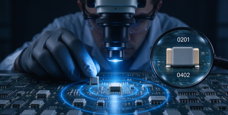
Deploy Multi‑Valued Parallel Decoupling: Instead of relying on a single bulk capacitor, parallel multiple smaller‑case MLCCs (such as 0402 or 0201) with staggered capacitance values. This broadens the effective frequency bandwidth and lowers total equivalent inductance.
Optimize Via Placement: Minimize mounting inductance by placing grounding and power vias directly adjacent to capacitor pads rather than running long, inductive traces.
Optimizing High‑Speed Performance with HLAIPOPNY
Mastering parasitic impedance is essential for designing robust, high‑frequency electronics that meet stringent electromagnetic compatibility (EMC) and signal integrity standards.
To explore our advanced inventory of low‑ESR, low‑ESL surface‑mount capacitors and verify technical specifications for your next high‑speed design, visit us at www.barronmlcc.com.
HLAIPOPNY — Empowering advanced high‑frequency engineering with high‑performance, precision‑engineered component solutions.
What maximum operating frequencies or data transfer rates are your current high‑speed circuit designs targeting?
Contact Us:
Email: hyc2355937758@gmail.com
WhatsApp:8615913754866
Tel: 86+18824523083
Website: www.barronmlcc.com
Inside the Layers Understanding MLCC Internal Voids Delamination and Destructive Physical Analysis DPA
Mitigating MLCC Acoustic Noise and Piezoelectric Effects in Audio and Power Circuits
Related Article