Decoding MLCC Specifications Interpreting Capacitance Tolerance Voltage Ratings and EIA Case Sizes
Decoding MLCC Specifications: Interpreting Capacitance Tolerance, Voltage Ratings, and EIA Case Sizes
When specifying Multilayer Ceramic Capacitors (MLCCs) for a new bill of materials (BOM), engineers must translate circuit requirements into precise component parameters. Misinterpreting a single data sheet metric can lead to inadequate power filtering, unexpected voltage breakdown, or components that simply do not fit onto the PCB layout.
For hardware designers and procurement specialists sourcing parts via www.barronmlcc.com, mastering the core specifications of ceramic capacitors ensures optimal performance, cost‑efficiency, and supply chain reliability.
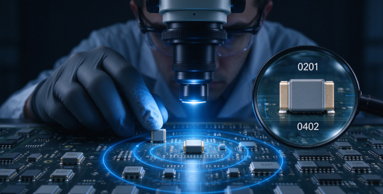
1. Demystifying EIA Case Sizes
MLCC dimensions are universally standardized using EIA (Electronic Industries Alliance) codes, which are expressed as a four‑digit number representing the length and width in hundredths of an inch.
Metric Equivalents: While imperial codes (e.g., 0402, 0603, 0805) remain standard in Western design nomenclature, metric equivalents (e.g., 1005, 1608, 2012) are frequently used globally. For example, an imperial 0603 measures 0.06 × 0.03 inches, corresponding to the metric 1608 (1.6 × 0.8 mm).
The Trade‑Off: Smaller case sizes (like 0201 or 0402) maximize board density and minimize parasitic inductance in high‑frequency loops, but they offer lower volumetric capacitance and are more susceptible to mechanical flex cracking. Larger cases (like 1206 or 1210) handle higher voltages and energy storage but require more real estate.
2. Navigating Capacitance Tolerance Codes
Capacitance tolerance defines the allowable percentage deviation from the nominal rated capacitance value under standard reference conditions (25°C and 1 Vrms). Different circuit applications demand varying levels of precision:
Class 1 (Precision) Codes: Tight tolerances are common here.
C (±0.25 pF): Used in ultra‑sensitive RF tuning and oscillator circuits.
D (±0.5 pF): Ideal for low‑value stray capacitance compensation.
J (±5%) and K (±10%): Standard tolerances for precision analog filtering.
Class 2 (General Purpose) Codes: Because Class 2 dielectrics undergo aging and voltage drift, wider tolerances are standard.
K (±10%): Common for standard decoupling lines.
M (±20%): Widely used for bulk power supply bypass where absolute precision is secondary to total available capacitance.
3. Working Voltage and Derating Rules
The Rated Voltage (Vdc) specified on an MLCC datasheet indicates the maximum continuous direct current voltage that can be applied across the terminals safely across the entire operating temperature range.
Safety Margins: Best engineering practice dictates applying a voltage derating rule—typically selecting a capacitor with a rated voltage at least double the actual working voltage present in the circuit.
The DC Bias Impact: As discussed in previous topics, Class 2 ceramics (like X7R and X5R) lose effective capacitance when subjected to DC voltage. Operating a capacitor close to its maximum rated limit dramatically accelerates this loss, sometimes shrinking effective capacitance by 50% or more. Always check manufacturer DC bias curves rather than relying solely on the nominal voltage stamp.
Elevating Component Selection with HLAIPOPNY
Navigating technical specifications requires precision at every stage of the design cycle. Choosing the right combination of case size, tolerance, and voltage rating protects your hardware from premature field failure.
To review comprehensive technical datasheets, check stock availability, and secure batch pricing for your active projects, visit us at www.barronmlcc.com.
HLAIPOPNY — Bridging the gap between rigorous engineering standards and reliable component supply chains.
What criteria do you typically weigh most heavily when balancing physical miniaturization against electrical performance constraints in your layout?
Contact Us:
Email: hyc2355937758@gmail.com
WhatsApp:8615913754866
Tel: 86+18824523083
Website: www.barronmlcc.com
Mitigating MLCC Acoustic Noise and Piezoelectric Effects in Audio and Power Circuits
Mastering MLCC Soldering Profiles Avoiding Thermal Shock and Tombstoning
Related Article