
MLCC Acoustic Noise Complete Solution Piezoelectric Effect Principle Circuit Suppression Structural Damping
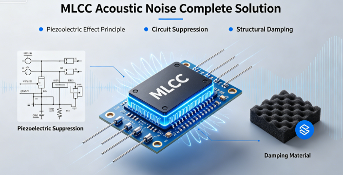
MLCC Acoustic Noise Complete Solution: Piezoelectric Effect Principle, Circuit Suppression & Structural Damping
Company: Dongguan Musen Laidun Electronic Technology Co., Ltd.
Keywords: MLCC Acoustic Noise, Capacitor Piezoelectric Effect, Power Supply Whistling, MLCC Noise Suppression, Structural Damping Design
mu sen Introduction
MLCC acoustic noise (whistling) is one of the most common and stubborn problems in the electronics industry, affecting almost all products from smartphones and laptops to automotive infotainment and industrial power supplies. It not only severely damages user experience but may also be accompanied by hidden issues such as circuit oscillation and efficiency degradation, leading to product returns and brand reputation damage.
Many engineers blindly replace capacitors or adjust circuit parameters without addressing the root cause: the piezoelectric effect of Class II ferroelectric dielectrics (X5R/X7R/X8R). When an alternating voltage is applied across an MLCC, the ceramic dielectric undergoes microscopic expansion and contraction. When the vibration frequency falls within the human audible range (20Hz~20kHz), audible noise is generated.
This article systematically analyzes the generation mechanism and influencing factors of MLCC acoustic noise starting from the physical principle of piezoelectric effect. It provides three categories of solutions: circuit optimization, material replacement, and structural damping, combined with real cases from consumer electronics, automotive, and industrial scenarios, offering practical and effective methods to completely solve MLCC noise problems.
1. The Nature of MLCC Acoustic Noise: Piezoelectric Effect & Vibration Transmission
1.1 Physical Principle of Piezoelectric Effect
The core dielectric of MLCC is barium titanate (BaTiO₃) based ferroelectric ceramic, which exhibits significant piezoelectric effect: when an electric field is applied, the ceramic unit cell deforms, causing microscopic expansion and contraction of the entire capacitor body. When the electric field alternates, the capacitor vibrates at the same frequency.
- Direct piezoelectric effect: Mechanical force generates electric charge (used in sensors)
- Converse piezoelectric effect: Electric field generates mechanical deformation (root cause of MLCC acoustic noise)
- Vibration amplitude: Proportional to applied voltage amplitude and dielectric piezoelectric coefficient
1.2 Noise Generation Process
- Alternating voltage in the 20Hz~20kHz range is generated in the circuit
- MLCC produces microscopic vibration at the same frequency under alternating voltage
- Vibration is transmitted to the PCB through solder pads
- PCB acts as a sounding board, amplifying and radiating vibration into the air
- Human ear receives sound waves and perceives it as whistling noise
1.3 Key Influencing Factors
| Influencing Factor | Effect on Acoustic Noise |
|---|---|
| Dielectric Type | X5R > X7R > X8R > C0G (C0G has no piezoelectric effect) |
| Voltage Amplitude | Higher voltage → larger vibration amplitude → louder noise |
| Voltage Frequency | Within 20Hz~20kHz, closer to 1kHz~5kHz (human sensitive range) → more annoying |
| Capacitance Value | Larger capacitance → larger ceramic volume → stronger vibration energy |
| Package Size | Large packages (1206 and above) are more prone to noise than small packages |
| PCB Structure | Thin and large-area PCBs are more likely to amplify vibration |
2. Level 1 Solution: Circuit Optimization (Most Cost-Effective)
Circuit optimization is the preferred solution for noise problems, with the lowest cost and significant effect. The core idea is to eliminate or reduce the alternating voltage component across the MLCC.
2.1 Adjust Switching Power Supply Operating Frequency
- Move the switching frequency outside the 20Hz~20kHz human audible range
- Recommended frequency: >25kHz (high frequency) or <20Hz (low frequency, pay attention to ripple)
- Note: Excessively high frequency will increase switching loss and reduce power efficiency
2.2 Optimize Loop Stability & Suppress Subharmonic Oscillation
- Many noise problems are caused by subharmonic oscillation due to unstable power supply loops
- Adjust compensation network parameters to increase phase margin (recommended ≥45°)
- Avoid discontinuous conduction mode (DCM), use continuous conduction mode (CCM) as much as possible
2.3 Adopt Multi-Stage Filtering Architecture
- Replace single large-capacity MLCC with "large-capacity electrolytic capacitor + small-capacity MLCC" combination
- Electrolytic capacitors absorb low-frequency ripple, MLCC absorbs high-frequency ripple, reducing alternating voltage across MLCC
- Can also use "MLCC + tantalum capacitor" combination, tantalum capacitors have much weaker piezoelectric effect than MLCC
2.4 Disperse Capacitor Layout to Reduce Vibration Superposition
- Avoid concentrating multiple large-capacity MLCCs in the same area
- Dispersed layout allows vibrations to cancel each other out, reducing overall PCB vibration
- Place noise-sensitive capacitors away from PCB edges and corners (where vibration amplification is most obvious)
3. Level 2 Solution: Material Replacement (Most Direct Effect)
If circuit optimization cannot completely solve the noise problem, consider replacing MLCC materials or types to reduce vibration generation at the source.
3.1 Replace with C0G Dielectric MLCC
- C0G dielectric is Class I paraelectric ceramic with no piezoelectric effect, the ultimate material solution for noise
- Advantages: Completely eliminates noise, excellent temperature stability, no aging
- Disadvantages: Low maximum capacitance (usually ≤1μF), higher cost
- Applicable scenarios: Small-capacity filtering, signal circuits, products with extremely high noise requirements
3.2 Use Low-Piezoelectric X8R Dielectric
- Some manufacturers offer low-piezoelectric X8R MLCCs with special formulations to reduce piezoelectric coefficient
- Advantages: Larger capacitance than C0G, lower cost than C0G, noise intensity reduced by 60%~80%
- Disadvantages: Cannot completely eliminate noise, still has slight noise
- Applicable scenarios: Medium-large capacity filtering, products with certain noise requirements but cost-sensitive
3.3 Use Other Types of Capacitors
- Tantalum capacitors: Extremely weak piezoelectric effect, large capacity, small size, but low voltage rating and high cost
- Aluminum electrolytic capacitors: No piezoelectric effect, large capacity, low cost, but large size, short life, poor high-frequency characteristics
- Film capacitors: No piezoelectric effect, good high-frequency characteristics, high voltage rating, but large size and high cost
3.4 Select Special Structure MLCC
- Metal terminal MLCC: Buffers vibration through metal terminals, reduces transmission to PCB
- Stacked MLCC: Optimized internal structure, smaller vibration amplitude
- Resin-encapsulated MLCC: External resin coating suppresses vibration radiation
4. Level 3 Solution: Structural Damping (Last Line of Defense)
If circuit optimization and material replacement cannot completely solve the noise problem, use structural damping measures to block vibration transmission paths and reduce noise radiation intensity.
4.1 Optimize PCB Design
- Increase PCB thickness (recommended ≥1.6mm) to improve rigidity and reduce vibration
- Add ground via array around noisy capacitors to increase local rigidity
- Avoid hollowing out under noisy capacitors, maintain PCB integrity
- Use multi-layer PCB design, increase power and ground plane thickness
4.2 Adhesive Reinforcement
- Apply epoxy resin or silicone adhesive between MLCC body and PCB
- Adhesive increases damping, absorbs vibration energy, reduces transmission to PCB
- Note: Adhesive must not cover solder pads; use high-temperature resistant and insulating adhesive
4.3 Add Damping Structures
- Stick damping pads or foam under noisy capacitors
- Use elastic connections (rubber pads, springs) between PCB and housing
- Stick sound-absorbing materials inside the housing to absorb radiated noise
4.4 Shielding & Isolation
- Cover severely noisy areas with metal shields
- Shields block noise radiation and increase PCB rigidity
- Ensure firm connection between shield and PCB to avoid resonance
5. Case Studies & Rectification for Different Scenarios
5.1 Consumer Electronics: Smartphone Fast Charger Noise
Problem: Sharp whistling noise from charger during fast charging
Root Cause: Power supply frequency falls into audible range during protocol switching; output filter MLCC has strong piezoelectric effect
Solution:
- Adjust switching frequency to 30kHz
- Replace 1206 X7R 10μF output filter with 0805 low-piezoelectric X8R
- Use "10μF electrolytic + 1μF MLCC" combined filtering
Result: Noise completely eliminated, power efficiency unchanged
5.2 Automotive Electronics: Infotainment Screen Noise
Problem: Buzzing noise during brightness adjustment
Root Cause: Backlight PWM dimming at 2kHz (human sensitive range); power decoupling MLCC generates vibration
Solution:
- Adjust PWM dimming frequency to 25kHz
- Replace backlight power decoupling capacitors with C0G dielectric
- Apply silicone adhesive around capacitors for damping
Result: Noise disappeared, dimming function normal
5.3 Industrial Power: Server Power Supply Noise
Problem: Obvious whistling at light load
Root Cause: Power supply operates in DCM mode at light load, generating subharmonic oscillation; DC-Link large-capacity MLCC vibrates strongly
Solution:
- Optimize control algorithm, automatically switch to CCM mode at light load
- Replace single 1210 47μF X7R with 4 dispersed 0805 10μF X8R
- Add stiffeners on PCB back to improve rigidity
Result: Light load noise eliminated, full load efficiency increased by 1%
6. Noise Troubleshooting & Resolution Process
- Locate noise source: Use a stethoscope or cotton swab to touch each capacitor and identify the noisiest one
- Analyze voltage waveform: Use an oscilloscope to measure voltage across the noisy capacitor, determine frequency and amplitude
- Circuit optimization: Prioritize adjusting power frequency, optimizing loop stability, and using multi-stage filtering
- Material replacement: If circuit optimization fails, replace with C0G or low-piezoelectric X8R
- Structural damping: Finally use adhesive, damping pads and other structural measures
- Verify effect: Test under different loads and temperatures to ensure complete noise elimination
7. Common Misconceptions & Pitfalls
- Misconception 1: Larger capacitance solves noise → Truth: Larger capacitance means stronger vibration energy, noise may worsen
- Misconception 2: X8R has no piezoelectric effect → Truth: X8R still has piezoelectric effect, just weaker than X5R/X7R
- Misconception 3: More adhesive = better damping → Truth: Excessive adhesive changes PCB stress distribution and may cause capacitor cracking
- Misconception 4: Noise is only a sound problem → Truth: Noise is often accompanied by circuit oscillation, which may damage devices long-term
- Misconception 5: All MLCCs make noise → Truth: C0G MLCCs have no piezoelectric effect and produce no noise
mu sen Conclusion
MLCC acoustic noise problems, while seemingly complex, have a clear solution path: circuit optimization first, then material replacement, and finally structural damping. The core is to eliminate the excitation of alternating voltage on MLCC at the source, or block the vibration transmission path.
Noise prevention should be considered during the product design stage: prioritize C0G or low-piezoelectric dielectrics, design reasonable power supply frequencies, disperse capacitor layouts, and optimize PCB structures. This avoids cost increases and schedule delays caused by later rectification.
Dongguan Musen Leyton Electronic Technology Co., Ltd. provides a full series of low-noise MLCC products, including high-precision C0G, low-piezoelectric X8R, and metal terminal damping types, meeting noise suppression requirements in different scenarios. We also provide professional noise analysis and rectification services to help customers quickly solve MLCC acoustic noise problems.
MLCC Sulfuration Failure Prevention Corrosion Mechanism Failure Characteristics High/Low Resistance Sulfuration Material Selection All-Round Protection Solutions
PV Energy Storage MLCC Full Scenario Selection Outdoor Reliability Protection for Inverter PCS Battery Cluster
Related Article




