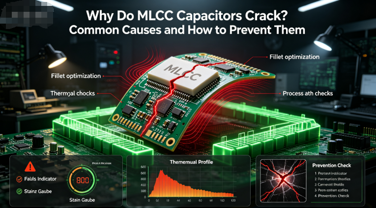
MLCC Failure Modes Explained Root Causes of Short Circuit vs Open Circuit Failures
MLCC Failure Modes Explained: Root Causes of Short‑Circuit vs. Open‑Circuit Failures
For reliability engineers, quality assurance managers, and failure analysis technicians, understanding how Multi‑Layer Ceramic Capacitors (MLCCs) fail is critical to preventing catastrophic field returns. While ceramic capacitors are renowned for their reliability and long operational lifespan under normal conditions, extreme electrical stress, manufacturing flaws, or environmental overloads can trigger distinct failure modes.
Analyzing whether an MLCC fails as a short circuit or an open circuit helps engineering teams diagnose root causes and implement robust design safeguards.
1. The Short‑Circuit Failure Mode (The Most Critical Risk)
By far the most hazardous and frequently encountered failure mode in ceramic capacitors is a low‑resistance short circuit.
The Mechanism: When an internal dielectric breakdown occurs, conductive paths form through the ceramic layers, bridging the internal opposing metal electrodes (nickel or copper).
Thermal Runaway and Safety Hazards: When a short‑circuit failure happens in a live power rail, the low resistance allows excessive current to flow through the component. This localized current concentration generates intense heat, often resulting in severe board burning, smoke, or component charring. In high‑power automotive or industrial systems, a shorted MLCC can pose a fire hazard if safety fuses or overcurrent protections do not trip quickly.
Primary Root Causes:
- Exceeding the maximum rated DC voltage, causing dielectric punch‑through.
- Severe mechanical micro‑cracks that propagate across internal electrode layers.
- Manufacturing defects or internal voids exacerbated by thermal shock during SMT reflow.
2. The Open‑Circuit Failure Mode
Open‑circuit failures occur when the electrical connection inside the capacitor or between the component and the PCB is completely severed, resulting in infinite resistance and zero capacitance.
The Mechanism: Unlike short circuits, open circuits rarely originate from deep within the bulk ceramic dielectric material itself. Instead, they typically stem from mechanical separation at the terminations.
Primary Root Causes:
- Extreme Board Flexing: Severe mechanical bending during board depanelization, shipping drops, or screw torquing can snap the metallic outer terminations or shear the solder joints entirely away from the PCB pad.
- Thermal Fatigue: Repeated thermal cycling over years of operation can induce fatigue cracking in rigid solder joints, eventually breaking the electrical bond.
- Incorrect Solder Profile: Insufficient solder paste volume or poor wetability during reflow can create weak, brittle joints that separate under minimal physical strain.
3. Engineering Strategies to Prevent MLCC Failures
To eliminate both short‑circuit and open‑circuit risks in commercial and industrial product designs, engineering and procurement teams should follow these best practices:
- Implement Generous Voltage De‑Rating: Never operate MLCCs close to their absolute maximum voltage threshold. Applying a safety margin (such as using a 50V rated capacitor on a 12V or 24V rail) significantly reduces long‑term dielectric degradation and prevents voltage spike punctures.
- Specify Flexible / Soft Terminations: For high‑stress areas near connectors, mounting holes, or board edges, procure MLCCs equipped with flexible polymer layer terminations. These layers act as shock absorbers, preventing mechanical strain from fracturing the ceramic body into a short circuit.
- Optimize SMT and Depanelization Processes: Eliminate manual board snapping and utilize advanced router or laser depanelization systems to prevent mechanical shock transmission to sensitive components.
Source High‑Reliability MLCCs with Proven Quality Assurance
Ensure your electronic assemblies remain robust against electrical and mechanical stress with premium surface‑mount components from barronmlcc.com. We supply fully tested, industry‑compliant MLCCs designed to meet strict international standards. Contact our technical sales engineering team today for data sheets, custom quotes, and reliable supply chain support.
Direct Email: hyc2355937758@gmail.com
WhatsApp & Mobile: +86 15913754866
Telephone Support: +86 18824523083
Official Web Portal: //www.barronmlcc.com
How to Choose an MLCC Capacitor for Automotive Electronics A Practical Selection Guide
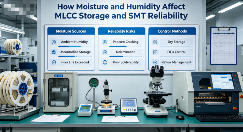
How Moisture and Humidity Affect MLCC Storage and SMT Reliability

Related Article
