
MLCC for High-Frequency Power Supplies SiC/GaN Adaptation High-Frequency Filtering Low-Loss Selection
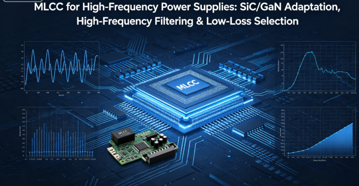
MLCC for High-Frequency Power Supplies: SiC/GaN Adaptation, High-Frequency Filtering & Low-Loss Selection
mu sen Introduction
With the wide application of SiC and GaN power devices, power supply operating frequencies have increased to 5MHz–20MHz. Traditional standard MLCCs cannot meet high-frequency operating conditions, often causing problems such as excessive loss, resonance interference, thermal failure, and unstable regulation.
For high-frequency applications, parasitic parameters, dielectric characteristics, and package size are critical to efficiency and stability. High-frequency power supplies require four core indicators: low ESR, low ESL, high SRF, and excellent capacitance retention at high frequencies. Conventional X5R, standard X7R, and large packages cannot meet the requirements of fast chargers, inverters, and energy-storage power supplies.
This article explains MLCC selection logic for high-frequency power supplies, adaptation rules for SiC/GaN circuits, combined filtering design, stress protection, and reliability optimization to solve resonance, heating, and EMI issues.
1. MLCC Performance Trends in High-Frequency Conditions
1.1 Electrical Changes with Increasing Frequency
- Capacitance attenuation: Effective capacitance drops rapidly for conventional dielectrics
- Increased loss: ESR rises with frequency, causing heat generation
- Parasitic dominance: ESL becomes dominant and causes resonance spikes
- Impedance transition: Beyond SRF, capacitor acts as an inductor and loses filtering function
1.2 Forbidden Components in High-Frequency Applications
- X5R dielectric: High loss and poor temperature stability
- Packages 1210 and above: High ESL and severe parasitic interference
- Old expired inventory: Degraded high-frequency performance
2. Precise MLCC Dielectric & Package Selection
2.1 Dielectric Selection by Frequency
| Operating Frequency | Recommended Dielectric | Core Advantages | Application Circuits |
|---|---|---|---|
| 1–5MHz | Standard X7R | Cost-effective, controllable loss | General fast chargers, low-voltage inverters |
| 5–10MHz | High-Frequency X8R | Low loss, stable at high temp & freq | GaN chargers, automotive power |
| Above 10MHz | C0G | No drift, ultra-low parasitics | High-frequency oscillation, sampling |
2.2 Package Selection Principles
Higher frequency requires smaller packages to minimize ESL:
- Below 10MHz: 0603 preferred (balance of current & parasitics)
- Above 10MHz: 0402 preferred (optimal response)
- High-current bus: Parallel small capacitors instead of single large package

3. MLCC Application for SiC/GaN Power Circuits
3.1 Snubber Capacitors for Switches
Used to suppress voltage spikes and protect devices. Select C0G (100pF–1nF), placed close to device pins with very short traces.
3.2 Input & Output Filter Design
- Combined filter: X8R for low-frequency ripple, C0G for high-frequency noise
- Parallel arrangement: Distributes ripple current and reduces heating
- Voltage derating: ≥1.8x for high-frequency spike environments
3.3 Gate Drive Circuit Requirements
Must use high-precision C0G dielectric with tolerance ≤±1% to avoid frequency shift and false triggering.

4. High-Frequency PCB Layout & Pad Design
4.1 Layout Rules
- Place MLCCs close to power IC pins to minimize loop area
- Keep traces short and direct; avoid long meandering paths
- Connect filter capacitor grounds directly to main ground plane
4.2 High-Frequency Pad Optimization
- Minimize pad length to reduce parasitic inductance
- Widen pad width for better heat dissipation
- Maintain spacing between capacitors to avoid coupling
5. High-Frequency Fault Troubleshooting & Solutions
5.1 Excessive Heating & Low Efficiency
Cause: High dielectric loss, high ESL, overload
Solution: Replace with X8R/C0G; use parallel capacitors
5.2 Circuit Resonance & Instability
Cause: SRF falls within operating band
Solution: Use smaller packages with higher SRF; adjust value combination
5.3 EMI Failure
Cause: Poor high-frequency filtering, large radiation loop
Solution: Multi-value filtering; compact layout; low-loss dielectrics
5.4 Excessive Switching Spike Voltage
Cause: Poorly matched snubber capacitor
Solution: Use C0G snubber; optimize placement and discharge path
6. Incoming Inspection Standards for High-Frequency MLCC
- Basic parameters: Capacitance tolerance meets dielectric standard
- Parasitic parameters: ESR / ESL below datasheet limits
- Resonance frequency: SRF higher than maximum operating frequency
- Thermal stability: Stable capacitance after aging at 125℃
mu sen Application Summary
MLCC design for high-frequency power supplies focuses on low parasitics, low loss, and high stability. Select dielectrics and packages based on operating frequency, use combined filtering, and compact PCB layout to fully adapt to SiC/GaN applications.
Abandoning low-frequency selection logic prevents heating, resonance, and interference, improving efficiency and long-term reliability.
Our full series of high-frequency MLCCs includes 0402/0603 packages, low-loss X8R, and high-precision C0G types, supporting all high-frequency power supply designs with selection support and free samples.


Contact Us
Automotive-grade certified high and low temperature shock resistant powertrain cabin selection surface mount capacitors
MLCC Failure Analysis Ultimate Troubleshooting Manual Complete Solutions for Cracking Breakdown Leakage Whistling Heating
Related Article




