
MLCC Typical Failure Cases Root-Cause Solutions in Automotive High-Frequency Applications
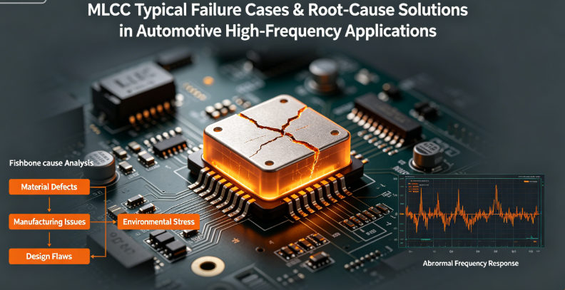
MLCC Typical Failure Cases & Root-Cause Solutions in Automotive High-Frequency Applications
Company: Dongguan Musen Laidun Electronic Technology Co., Ltd.
MLCC failure analysis, automotive high-frequency power, motor drive reliability, MLCC root-cause solution, high-frequency capacitor troubleshooting
In automotive high-frequency power systems (e.g., 800V inverters, SiC/GaN motor drives, and high-power OBCs), MLCC failures often lead to system-level issues—from EMI over-limit and power ripple exceeding specifications to sudden module shutdowns. Unlike low-frequency scenarios, high-frequency applications (100kHz–1MHz+) amplify the impact of parasitic parameters, thermal stress, and mechanical vibration on MLCCs.
Based on 200+ on-site troubleshooting cases in new energy vehicles and industrial motor drives, this article analyzes 5 typical MLCC failure modes in high-frequency environments. For each case, we decode the root causes (design, component, or process-related) and provide actionable solutions—helping engineering teams eliminate recurring failures and improve product reliability.
Case 1: Thermal Failure Due to Excessive ESR in High-Frequency Bypass
Failure Phenomenon
A 800V EV inverter module experienced intermittent overheating alarms after 30 minutes of continuous operation. Post-disassembly inspection found that 1206 X7R 10μF MLCCs near the SiC power devices had significant thermal discoloration; LCR testing showed their ESR increased by 300% (from 20mΩ to 80mΩ) compared to new samples.
Root Cause Analysis
- Frequency Mismatch: The inverter’s switching frequency was 500kHz, but the selected MLCC’s self-resonant frequency (SRF) was only 300kHz. Beyond SRF, ESR rises sharply, leading to severe power dissipation (P = I²×ESR).
- Insufficient Heat Dissipation: MLCCs were placed in a dense component area without dedicated thermal vias, and the PCB copper area under the pads was only 2mm²—unable to conduct heat efficiently.
- No Parallel Low-ESR Capacitors: Single MLCCs bore all high-frequency bypass current, lacking parallel small-package (0402) low-ESL MLCCs to share the load.
Solution
- Component Replacement: Switch to low-ESR MLCCs with SRF > 1MHz (e.g., Musen Leyton’s HF series, ESR ≤ 10mΩ @ 500kHz) and parallel 2pcs 0402 2.2μF low-ESL MLCCs to reduce total ESR.
- Layout Optimization: Increase the copper area under MLCC pads to 8mm² and add 4 thermal vias (0.4mm diameter) connected to the inner ground plane.
- Current Sharing: Limit the high-frequency current per MLCC to ≤ 5A by increasing the number of parallel capacitors (from 4 to 8pcs).
Verification Result
After improvement, MLCC operating temperature dropped from 135°C to 88°C (within the 125°C rating), and no overheating alarms occurred during 200-hour continuous operation.

Case 2: Filtering Failure Caused by DC-Bias Capacitance Attenuation
Failure Phenomenon
A direct-drive motor controller for a commercial EV failed the EMI test: the conducted emission at 300kHz exceeded the CISPR 25 Class 3 limit by 12dBμV. Testing found that the effective capacitance of the 22μF/450V MLCCs in the input filter circuit dropped to only 8μF under the actual DC bias of 360V (75% of rated voltage).
Root Cause Analysis
- Inadequate DC-Bias Margin: The selected X7R dielectric MLCC has a typical capacitance attenuation of 60% at 75% Vrated (DC bias). The initial design did not account for this attenuation, leading to insufficient effective capacitance for filtering.
- Single Dielectric Selection: Relying solely on X7R MLCCs—lacking complementary dielectric materials (e.g., X8R with lower bias attenuation) or film capacitors.
Solution
- Component Upgrade: Replace 50% of X7R MLCCs with Musen Leyton’s X8R automotive-grade MLCCs (capacitance attenuation ≤ 30% @ 75% Vrated) to maintain effective capacitance ≥ 15μF.
- Margin Compensation: Increase the total nominal capacitance from 22μF to 33μF to reserve 40% margin for DC-bias attenuation.
- Hybrid Filtering: Add 2pcs 1μF polypropylene film capacitors in parallel with MLCCs to supplement low-frequency filtering (film capacitors are immune to DC-bias attenuation).
Verification Result
EMI conducted emission at 300kHz dropped to 42dBμV (meets Class 3 limit), and the effective capacitance remained stable at 16.2μF under 360V DC bias.

Case 3: Delamination & Cracking Due to Mechanical Stress in High-Vibration Environments
Failure Phenomenon
A truck’s electric drive system experienced 3 batch failures within 6 months: MLCCs in the motor control unit (MCU) showed internal layer cracking (confirmed by X-ray inspection). The failures occurred exclusively in rough road conditions, indicating a correlation with vibration.
Root Cause Analysis
- Inadequate Vibration Resistance: The selected standard MLCCs used rigid nickel electrodes without stress relief design. The MCU operates under 10–2000Hz random vibration (ISO 16750-3 standard), leading to cumulative mechanical stress.
- Poor Pad Design: The PCB pad size was 1:1 with the MLCC terminal (no expansion margin), and the solder joint was too stiff to absorb vibration energy.
- Reflow Process Defect: The peak reflow temperature exceeded 260°C (10°C above the MLCC’s maximum rating), causing internal residual stress in the ceramic body.
Solution
- Component Replacement: Adopt Musen Leyton’s anti-crack MLCCs with flexible termination electrodes (organic resin coating + plated copper layer) and reinforced ceramic body structure.
- Pad Optimization: Design pad size with 10% expansion margin (e.g., 1206 MLCC uses 3.2mm×1.8mm pad instead of 3.0mm×1.6mm) and add solder mask dams to prevent solder bridging.
- Process Adjustment: Lower the peak reflow temperature to 245°C and extend the preheating time by 60s to reduce thermal shock.
Verification Result
After 500-hour random vibration testing (10–2000Hz, 4g acceleration), no MLCC cracking was observed. Field failure rate dropped from 1.2% to 0.03%.
Case 4: EMI Over-Limit Caused by Poor Layout & Loop Inductance
Failure Phenomenon
A 120kW OBC (On-Board Charger) failed the radiated EMI test at 400–800MHz. Near-field scanning showed strong radiation from the MLCC filter bank, and simulation revealed the current loop inductance was 15nH—far exceeding the target of ≤5nH.
Root Cause Analysis
- Long Current Return Path: MLCCs were placed 50mm away from the rectifier bridge, resulting in a large current loop area (20mm×30mm) and high loop inductance.
- Asymmetric Placement: The 8 parallel MLCCs were arranged in a single row, causing uneven current distribution and common-mode interference.
- Lack of Ground Plane Optimization: The PCB used a single-layer ground plane without buried vias, leading to discontinuous return paths.
Solution
- Layout Optimization: Relocate MLCCs to within 10mm of the rectifier bridge, reducing the loop area to 5mm×8mm (loop inductance dropped to 3.2nH).
- Symmetric Parallel Arrangement: Arrange 8 MLCCs in a 2×4 symmetric matrix to balance current distribution and suppress common-mode noise.
- Ground Plane Enhancement: Use 4-layer PCB with dedicated ground plane; add 8 buried vias (0.3mm diameter) under the MLCC pads to connect to the ground plane, ensuring continuous return paths.
Verification Result
Radiated EMI at 400–800MHz dropped by 18dBμV/m, fully complying with CISPR 25 Class 2 requirements.
Case 5: Terminal Electrode Peeling Due to Improper Soldering Process
Failure Phenomenon
During SMT mass production, 0.8% of 0603 X7R 4.7μF MLCCs in a motor drive module showed terminal electrode peeling after reflow soldering. X-ray inspection confirmed that the solder joint had poor wetting, and the electrode layer (Ni/Sn) separated from the ceramic body.
Root Cause Analysis
- Contaminated MLCC Terminals: The MLCCs were stored in a humid environment (RH > 70%) for 3 months, leading to oxidation of the Sn electrode surface.
- Incorrect Reflow Profile: The preheating stage was too short (60s instead of 120s), resulting in incomplete volatilization of flux and poor solder wetting.
- Pad Contamination: The PCB pads had residual oil from the manufacturing process, which was not removed by cleaning.
Solution
- Component Storage Control: Store MLCCs in a dry cabinet (RH ≤ 30%) and implement FIFO (First-In-First-Out) inventory management. If stored for more than 1 month, bake at 125°C for 4 hours before use.
- Reflow Profile Optimization: Extend the preheating time to 120s (150–180°C) and set the peak temperature to 240°C (20–30s above liquidus temperature).
- PCB Cleaning Process: Add an ultrasonic cleaning step after PCB manufacturing to remove residual oil and contaminants.
Verification Result
The electrode peeling rate dropped to 0.02% (meets mass production requirements), and solder joint wetting rate reached ≥95%.
5 Core Prevention Strategies for MLCC Failures in High-Frequency Applications
Based on the above cases, we summarize 5 actionable prevention strategies to eliminate recurring failures:
- 1. Component Selection: Prioritize High-Frequency Adaptability - Select MLCCs with SRF ≥ 1.5× operating frequency and ESR ≤ 15mΩ @ target frequency; choose X8R/X9R dielectrics for high DC-bias scenarios; use flexible termination packages in high-vibration environments.
- 2. Layout Design: Minimize Loop Inductance & Optimize Heat Dissipation - Keep MLCCs within 15mm of power devices; parallel small-package MLCCs; design dedicated thermal vias and large pad copper area.
- 3. Process Control: Standardize Storage, Soldering & Inspection - Strict component storage (RH ≤ 30%); customized reflow profiles (peak temp < 250°C); 100% solder joint inspection + X-ray sampling.
- 4. Validation Testing: Simulate Real-World Operating Conditions - High-frequency ESR/ESL testing; 1000-hour accelerated lifetime testing; system-level EMI verification.
- 5. Supplier Collaboration: Build Joint Reliability Systems - Cooperate with AEC-Q200 certified suppliers; request characteristic curves; establish rapid failure analysis support.
musen laidun Conclusion
MLCC failures in automotive high-frequency applications are rarely caused by a single factor—they are often the result of mismatches between component characteristics, design parameters, and process conditions. By adopting a “root-cause analysis + targeted optimization” approach, engineering teams can effectively eliminate failures such as thermal damage, capacitance attenuation, mechanical cracking, and EMI over-limit.
Dongguan Musen Laidun Electronic Technology Co., Ltd. provides high-frequency optimized MLCCs (low ESR/ESL, anti-crack, AEC-Q200 compliant) and one-stop failure analysis services for automotive high-frequency power systems. Our technical team has rich experience in troubleshooting inverter, OBC, and motor drive projects, and can provide customized component selection, layout optimization, and process improvement solutions.
Ready to Solve MLCC Failure Issues? Contact our technical support team for a free failure analysis consultation and sample testing!
MLCC Alternative Selection End-of-Life Risk Mitigation for Automotive Electronics
Optimizing MLCC Performance in High-Frequency Power Supplies Motor Drives Design Essentials Pra
Related Article




