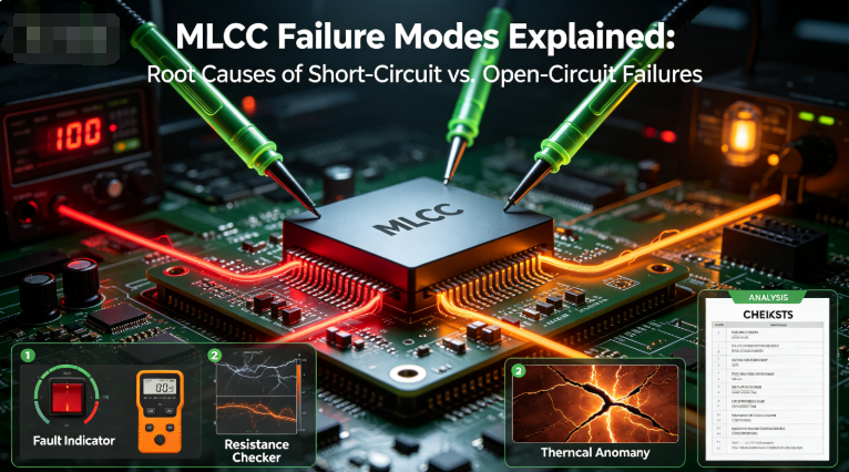
Why Do MLCC Capacitors Crack Common Causes and How to Prevent Them

Why Do MLCC Capacitors Crack? Common Causes and How to Prevent Them
MLCC capacitors are small, reliable, and widely used in electronic devices. However, one problem can cause serious trouble during PCB assembly or after the product has been put into use: MLCC cracking.
A cracked MLCC may look like a small physical defect, but it can affect the electrical performance of the capacitor. In some cases, the problem may not be discovered immediately. The capacitor may pass an initial inspection and fail later during testing or operation.
So, why do MLCC capacitors crack?
The answer is usually related to mechanical stress, PCB bending, soldering conditions, temperature changes, or component selection.
This article explains the common causes in simple terms and provides practical ways to reduce the risk.
What Is an MLCC Crack?
An MLCC is made from multiple thin ceramic layers stacked together.
The ceramic material provides good electrical performance, but it is also relatively hard and brittle compared with some other electronic materials.
When excessive mechanical stress is applied to the component, a small crack can develop inside the ceramic body.
The crack may not always be visible from the outside.
This is one reason MLCC cracking can be difficult to identify during normal visual inspection.
A small internal crack can sometimes create a path for current leakage. In more serious cases, it may eventually lead to insulation failure or a short circuit.
1. PCB Bending Is a Common Cause
One of the most common causes of MLCC cracking is PCB bending.
Imagine a ceramic capacitor soldered firmly to a circuit board.
If the board bends, the capacitor cannot simply follow the movement of the PCB. Mechanical stress is transferred through the solder joints to the ceramic body.
If the stress is high enough, the ceramic layers can crack.
PCB bending can happen during:
- PCB assembly
- Depanelization
- Connector insertion
- Screw fastening
- Product assembly
- Maintenance
- Handling
For example, if an operator pushes down on a PCB while installing a connector, the board may bend. The pressure may be transferred to nearby MLCCs.
The capacitor may appear normal afterward, but an internal crack could already exist.
2. Depanelization Can Damage MLCCs
During PCB manufacturing, multiple circuit boards are often produced together as one large panel.
After assembly, the individual boards need to be separated.
This process is called depanelization.
If too much mechanical force is applied during depanelization, the PCB can flex or vibrate.
MLCCs located close to the separation area may experience greater mechanical stress.
This is why component placement matters.
Whenever possible, designers should avoid placing larger or mechanically sensitive MLCCs too close to areas where the PCB will be cut or separated.
3. Hand Soldering Can Create Problems
Hand soldering is another area that requires attention.
If a soldering iron is applied incorrectly or for too long, the component can experience a rapid temperature change.
Ceramic materials do not respond well to sudden temperature differences.
For example, if one side of an MLCC becomes very hot while the other side remains relatively cool, thermal stress can develop inside the component.
This can increase the risk of cracking.
For production environments, following the component manufacturer's recommended soldering profile is important.
4. Rapid Temperature Changes Can Stress the Ceramic
MLCCs can also experience stress from rapid heating and cooling.
This is known as thermal shock.
Consider a simple example.
A PCB is heated during soldering. Afterward, it is exposed to a much cooler environment too quickly.
The different parts of the component and PCB may expand or contract at different rates.
Because the ceramic, metal electrodes, solder, and PCB have different material properties, stress can develop around the MLCC.
A controlled heating and cooling process can help reduce this risk.
5. Large MLCC Packages Need Extra Attention
Larger MLCC packages can provide higher capacitance and other useful electrical characteristics.
However, larger ceramic components may also be more sensitive to mechanical stress.
This does not mean that large MLCCs are unsuitable for demanding applications.
Instead, the PCB design and assembly process should take their mechanical characteristics into account.
The larger the component, the more important it becomes to consider:
- PCB bending
- Component location
- Soldering conditions
- Board thickness
- Depanelization method
- Mechanical assembly forces
The correct solution is not always to use a smaller capacitor. The component and PCB should be designed as a complete system.
6. Soldering Conditions Matter
The soldering process can affect MLCC reliability.
During reflow soldering, the PCB and components are exposed to high temperatures.
If the heating process is not properly controlled, the MLCC may experience excessive thermal stress.
Uneven soldering can also create mechanical stress.
For this reason, manufacturers should follow the recommended reflow profile provided by the MLCC supplier.
Important factors include:
- Heating rate
- Peak temperature
- Time above liquidus
- Cooling rate
- Solder volume
- Pad design
The exact requirements depend on the MLCC and soldering process, so the component manufacturer's technical documentation should be followed.
7. Board Design Can Reduce Cracking Risk
MLCC reliability does not depend only on the capacitor itself.
The PCB layout also plays an important role.
Engineers should consider where the capacitor is placed and how mechanical forces move through the board.
For example, placing an MLCC near a PCB edge, screw hole, connector, or depanelization line may expose it to greater mechanical stress.
A better layout can reduce the amount of stress transferred to the component.
This is particularly important for applications where long‑term reliability is critical.
8. Why Can a Cracked MLCC Pass Inspection?
This is a common question.
A small crack may be located inside the ceramic body and may not be visible during a normal visual inspection.
The capacitor can therefore look perfectly normal.
The problem may only become noticeable through electrical testing or after the product has operated for some time.
Depending on the location and severity of the crack, the component may show:
- Increased leakage current
- Reduced insulation resistance
- Electrical instability
- Short‑circuit failure
This is why preventing mechanical damage is usually better than relying only on final visual inspection.
9. How Can Manufacturers Reduce MLCC Cracking?
There is no single solution that works for every PCB.
However, several practical steps can reduce the risk.
Use Appropriate PCB Handling Methods
Avoid pressing, bending, or twisting the PCB unnecessarily during assembly.
Operators should handle boards carefully, especially after MLCCs have been soldered.
Review Component Placement
Avoid placing sensitive MLCCs in areas where the PCB experiences high mechanical stress.
Pay particular attention to:
- PCB edges
- Connector areas
- Screw holes
- Depanelization lines
- Board fixing points
Control the Reflow Process
Use the recommended soldering profile. Avoid excessive heating or rapid temperature changes.
Review the Depanelization Method
If cracking problems appear after PCB separation, review the depanelization process. The cutting method, cutting direction, tool condition, and component location can all affect mechanical stress.
Consider Soft‑Termination MLCCs
For applications with higher mechanical reliability requirements, engineers may consider MLCCs with soft termination or flexible termination structures.
These designs can help reduce the mechanical stress transferred from the PCB to the ceramic body.
The exact performance depends on the product construction and manufacturer specifications.
10. How to Identify a Possible MLCC Cracking Problem
If an MLCC‑related failure occurs after PCB assembly, do not immediately assume that the capacitor itself is defective.
The assembly process should also be investigated.
A useful troubleshooting process is:
Step 1: Identify when the failure occurs.
Does the problem appear after reflow, depanelization, testing, or final assembly?
Step 2: Check the component location.
Are the failed MLCCs concentrated near connectors, board edges, screws, or cutting areas?
Step 3: Compare different PCB batches.
If failures suddenly increase in one production batch, check whether the assembly process has changed.
Step 4: Perform electrical testing.
Check parameters such as insulation resistance and leakage current.
Step 5: Inspect failed components.
Microscopic inspection and other failure‑analysis methods may be required to identify internal cracks.
This process helps distinguish a component‑quality issue from a PCB assembly problem.
11. What Should You Ask an MLCC Supplier?
If you are purchasing MLCCs for a high‑reliability application, it is useful to ask the supplier about more than capacitance and voltage.
You can ask:
- What package sizes are available?
- What temperature range is supported?
- Is the product suitable for automotive or industrial applications?
- Is soft termination available?
- What soldering profile is recommended?
- What reliability tests are performed?
- Can the supplier provide samples for evaluation?
- What quality control procedures are used during production?
A good supplier should be able to provide clear technical information rather than only a price quotation.
FAQ
Can an MLCC work normally after it has cracked?
It may continue to work for some time, depending on the location and severity of the crack. However, a cracked ceramic body can reduce long‑term reliability and may lead to electrical failure.
Are larger MLCCs more likely to crack?
Larger MLCC packages can be more sensitive to mechanical stress. However, cracking depends on many factors, including PCB design, component construction, assembly conditions, and handling.
Can reflow soldering cause MLCC cracking?
Yes. Improper heating or cooling conditions can create thermal stress. Following the recommended soldering profile can help reduce the risk.
Can PCB bending damage an MLCC?
Yes. PCB bending is one of the important mechanical causes of MLCC cracking, particularly when the capacitor is located in a high‑stress area.
How can I reduce MLCC cracking during PCB assembly?
Start by controlling PCB handling, component placement, depanelization, and soldering conditions. For applications with higher mechanical requirements, specialized MLCC structures such as soft termination may also be considered.
Conclusion
MLCC cracking is usually not caused by one factor alone.
The capacitor, PCB design, soldering process, mechanical assembly, and handling method can all affect the final reliability of the component.
The good news is that many cracking problems can be reduced by identifying mechanical stress early and improving the PCB assembly process.
When selecting an MLCC, do not look only at capacitance, voltage, and price. Consider how the capacitor will actually be mounted, handled, soldered, and used.
A good MLCC design is not only about choosing the right electrical specifications. It is also about making sure the component can survive the real‑world conditions of the finished product.
Contact Barron‑Leiden for High‑Reliability MLCC Solutions
Email: hyc2355937758@gmail.com
WhatsApp: +86 15913754866
Tel: +86 18824523083
Website: www.barronmlcc.com
How to Choose an MLCC Capacitor for Automotive Electronics A Practical Selection Guide
Related Article