Demystifying MLCC Aging Why Class 2 Capacitors Lose Capacitance Over Time
Demystifying MLCC Aging: Why Class 2 Capacitors Lose Capacitance Over Time
When designing circuits with Multilayer Ceramic Capacitors (MLCCs), engineers carefully calculate capacitance values to ensure stable filter cutoffs, clean power rails, and precise timing. However, if your design relies on Class 2 ceramic formulations like X7R or X5R, you may notice a subtle phenomenon: the capacitance gradually decreases over time, even when the component sits idle on a shelf.
For hardware designers and procurement specialists sourcing components via www.barronmlcc.com, understanding the aging phenomenon is essential for predicting long‑term product reliability and preventing performance drift in mission‑critical hardware.
1. The Physics Behind MLCC Aging
Unlike Class 1 capacitors (such as C0G/NP0) which feature stable temperature‑compensating dielectrics, Class 2 MLCCs are built using ferroelectric materials—predominantly barium titanate ($BaTiO_3$).
- Domain Structure Reorientation: Below their Curie temperature, the crystal lattice of barium titanate organizes into localized polarized regions called ferroelectric domains.
- The Decay Over Time: Immediately after manufacturing or after being heated above the Curie point (during soldering reflow, for instance), these domains are in a highly dynamic, energetic state. Over time, mechanical and thermal stresses cause these domains to gradually lock into lower‑energy configurations.
- The Result: As more domains stabilize and lose their ability to freely reorient under an electric field, the bulk dielectric permittivity drops, manifesting as a measurable loss in total capacitance.
2. Quantifying the Aging Rate (The "Decade Hour" Rule)
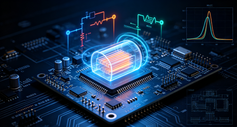
Capacitance loss in Class 2 MLCCs does not happen linearly; it occurs logarithmically with respect to time, typically measured in decades of hours.
The Timeline: A decade hour represents a tenfold increase in time elapsed since the last thermal reset.
1 hour
10 hours ($0.42$ days)
100 hours ($4.17$ days)
1,000 hours ($41.7$ days)
10,000 hours ($\approx 1.14$ years)
- Typical Aging Rates: Standard X7R and X5R dielectrics exhibit an aging rate ranging from 1.5% to 2.5% per decade hour. This means if a capacitor loses 2% of its capacitance between hour 10 and hour 100, it will lose another 2% between hour 100 and hour 1,000.
- The Reset Mechanism: If an aged MLCC is heated above its Curie temperature (roughly $125^\circ\text{C}$ to $150^\circ\text{C}$ depending on the formulation) during solder reflow, the internal domain structure completely resets. The aging clock starts ticking over again from zero the moment the component cools down.
3. Design Strategies to Counteract Aging
Because aging is an inherent physical characteristic of ferroelectric ceramics, it cannot be stopped entirely, but its impact can be successfully managed:
- Allocate Guard Bands: When selecting Class 2 capacitors for precision filters or timing circuits, factor the maximum expected aging drift into your end‑of‑life (EOL) tolerance budget.
- Upgrade to Class 1 Where Possible: For circuits where capacitance stability is paramount (such as analog oscillators or sensitive RF matching networks), substitute Class 2 capacitors with C0G (NP0) variants, which experience zero aging drift.
- Source Tight‑Tolerance Batches: Work with trusted manufacturers who provide rigorous consistency in powder preparation and sintering to keep baseline tolerances tight.
Securing Long‑Term Stability with HLAIPOPNY
Managing component characteristics like DC bias and aging ensures your electronic designs maintain peak performance throughout their intended operational lifecycle.
To explore our comprehensive selection of high‑stability capacitors and verify batch specifications for your next production run, visit us at www.barronmlcc.com.
HLAIPOPNY — Engineering precision and long‑term reliability into every layer of modern electronics manufacturing.
Are your current hardware designs constrained primarily by physical size limitations, or by strict long‑term electrical stability requirements?
Contact Us:
EM: hyc2355937758@gmail.com
WhatsApp:8615913754866
Tel: 86+18824523083
Website: www.barronmlcc.com
Mastering MLCC Soldering Profiles Avoiding Thermal Shock and Tombstoning
Navigating MLCC Failures Understanding Thermal Cracks Flex Cracks and Mitigation Strategies
Related Article