Mastering MLCC Soldering Profiles Avoiding Thermal Shock and Tombstoning
Mastering MLCC Soldering Profiles: Avoiding Thermal Shock and Tombstoning
When manufacturing high‑density printed circuit boards (PCBs), the assembly phase is where component integrity is put to the ultimate test. Multilayer Ceramic Capacitors (MLCCs) are remarkably resilient when operating in the field, but they are vulnerable during the rapid thermal transitions of automated surface‑mount technology (SMT) reflow and wave soldering.
For manufacturing engineers and assembly technicians sourcing components through www.barronmlcc.com, understanding how to optimize soldering profiles is critical to preventing latent defects, micro‑cracks, and assembly yield losses.
1. The Danger of Aggressive Thermal Ramping
Thermal shock occurs when different regions of a component expand at drastically different rates due to an extreme temperature differential ($dT/dt$) over a short timeframe.
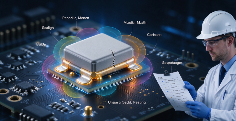
- The SMT Reflow Hazard: If a reflow oven ramps up temperature too aggressively during the preheat stage, the outer ceramic body of a large MLCC heats up much faster than the inner metal electrodes and dielectric layers.
- Internal Tensile Stress: This thermal gradient generates severe mechanical stress, often resulting in hidden micro‑cracks or complete structural delamination.
- The Reflow Profile Solution: Standard industry guidelines (such as IPC‑7531) recommend controlling preheat ramp rates—typically keeping temperature increases below $2^\circ\text{C}$ to $3^\circ\text{C}$ per second—to ensure uniform thermal saturation across both the PCB substrate and the ceramic components.
2. Preventing "Tombstoning" (Drawbridging)
Tombstoning occurs when an MLCC lifts off one of its solder pads during reflow, standing vertically like a miniature tombstone. This opens the circuit and causes immediate line fallout.
Asymmetrical Thermal Capacity: Tombstoning happens when one solder pad melts and wets before the other. The surface tension of the molten solder on the first pad pulls the component upward before the opposite side has a chance to anchor.
Layout and Process Triggers:
- Unequal Pad Sizes or Trace Widths: Connecting one pad to a heavy internal ground plane while the other connects to a narrow trace creates an uneven thermal mass. The narrow trace heats up and melts faster.
- Excessive Solder Paste: Applying too much paste on one pad creates an imbalance in surface tension forces during reflow.
Best Practices: Ensure balanced copper thermal routing on both pads and maintain precise, uniform stencil apertures during paste deposition.
3. Best Practices for Hand‑Soldering MLCCs
While automated SMT lines dominate volume production, rework and prototype assembly often require manual soldering irons. Improper technique here is a leading cause of field returns.
- Preheat the Board: Avoid applying a hot $350^\circ\text{C}$ iron directly to a cold PCB. Preheating the local area minimizes thermal shock.
- Control Dwell Time: Do not keep the soldering iron tip in direct contact with the MLCC metal termination for more than 3 to 5 seconds.
- Use Clean, Correct Tips: Ensure clean, well‑tinned chisel tips that transfer heat efficiently without requiring excessive physical force.
Optimizing Manufacturing Quality with HLAIPOPNY
Achieving zero‑defect SMT assembly requires a combination of disciplined process engineering and high‑grade, structurally sound components designed to withstand rigorous manufacturing profiles.
To explore our extensive inventory of high‑reliability surface‑mount capacitors and review technical datasheets for your production line, visit us at www.barronmlcc.com.
HLAIPOPNY — Delivering manufacturing excellence and uncompromising component reliability to the global electronics industry.
What specific reflow oven profiling tools or inspection methods (such as 3D AOI or X‑ray) do you rely on most heavily to catch assembly defects on your lines?
Contact Us:
EM: hyc2355937758@gmail.com
WhatsApp:8615913754866
Tel: 86+18824523083
Website: www.barronmlcc.com
Decoding MLCC Specifications Interpreting Capacitance Tolerance Voltage Ratings and EIA Case Sizes
Demystifying MLCC Aging Why Class 2 Capacitors Lose Capacitance Over Time
Related Article