Preventing SMT Manufacturing Defects Best Practices for Handling and Soldering MLCCs
Preventing SMT Manufacturing Defects: Best Practices for Handling and Soldering MLCCs
Even the highest-grade Multi-Layer Ceramic Capacitors (MLCCs) can fail prematurely if they suffer structural damage during the surface-mount technology (SMT) assembly process. Because ceramic bodies are inherently rigid and brittle, mechanical stress, rapid thermal shock, and poor PCB design are leading causes of latent failures in industrial electronics, automotive modules, and consumer hardware.
For manufacturing engineers and quality assurance teams, identifying and mitigating these assembly risks is essential to ensuring long-term product reliability.
The Physics of Ceramic Failure: Flex Cracking and Thermal Shock
Unlike tantalum or electrolytic capacitors that have flexible leads or plastic bodies, MLCCs feature ceramic dielectric layers sintered directly with internal metal electrodes. This rigid structure makes them vulnerable to two primary manufacturing hazards:
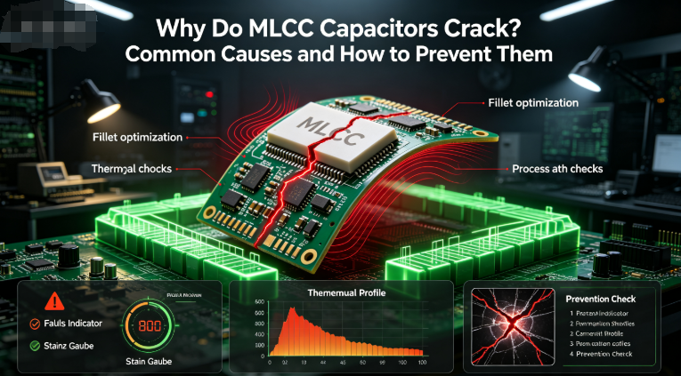
- PCB Mechanical Flexurual Stress: Printed circuit boards undergo mechanical bending during depanelization (V-score cutting, routing), connector insertion, screw fastening, and manual handling. When a PCB flexes, rigid components soldered directly to the pads are forced to bend with it. Because ceramic cannot stretch, the mechanical strain propagates through the solder joints and fractures the ceramic body, causing internal short circuits or catastrophic thermal runaway.
- Thermal Shock During Reflow: Exposing components to overly aggressive temperature gradients during infrared (IR) reflow or wave soldering induces severe thermal stress. The outer metal terminations heat up faster than the internal ceramic mass, creating differential expansion forces that result in micro-cracks.
Key SMT Process Guidelines to Protect MLCCs
To safeguard production lines and eliminate field failures caused by cracked capacitors, assembly facilities should enforce the following engineering controls:
- Optimize PCB Layout and Panel Design:
Avoid placing heavy or brittle MLCCs near high-stress areas such as board edges, V-score lines, mounting holes, and connectors.
If components must be placed near a breakaway edge or panel boundary, orient them parallel to the expected stress vector rather than perpendicular. - Refine the Reflow Thermal Profile: Ensure that preheat zones comply with manufacturer guidelines—typically limiting ramp-up rates to 2°C to 3°C per second. Sudden spikes in temperature shock the ceramic body and compromise termination integrity.
- Control Depanelization Stresses: Eliminate manual snapping or shearing methods for separating PCB panels. Instead, utilize laser cutting, router-based depanelization, or specialized V-cut blade systems that minimize physical board bending.
- Upgrade to Flexible Termination Options: For high-risk applications exposed to severe thermal cycling or mechanical vibration, consider specifying MLCCs equipped with flexible/soft terminations (conductive epoxy layers beneath the outer plating). These specialized terminations absorb physical strain and prevent crack propagation into the ceramic matrix.


Source Reliable, High-Quality MLCCs for Mass Production
Keep your assembly lines running smoothly with precision-manufactured surface-mount components from barronmlcc.com. We provide complete technical documentation, robust packaging solutions, and volume supply chain support tailored to international electronics manufacturers. Contact our technical sales engineering team today for professional advice, samples, and competitive quotations.
Get In Touch
Direct Email: hyc2355937758@gmail.com
WhatsApp & Mobile: +86 15913754866
Telephone Support: +86 18824523083
Official Web Portal: //www.barronmlcc.com
Understanding MLCC Dielectric Aging Why Class II Capacitors Lose Capacitance Over Time
Understanding MLCC DC Bias Characteristics Why Your Capacitance Drops in Power Supply Circuits
Related Article